Stuart Crisp, UK manager of Advanced Drainage Systems, considers best practices for under-structure attenuation systems.
Climate change is increasing the risk of flooding with all the negative impacts that such incidents bring to buildings, infrastructure and communities. The Environment Agency’s latest estimates show that while around 6.3 million properties in England are at risk of flooding today, this number could grow to 8 million by the middle of the century.
The need to consider resilience to climate change when designing our new buildings and developments is rightly moving up the agenda for authorities and for developers. Delivering resilience to flooding requires drainage engineers to deploy a whole toolbox of measures to help slow the flow of water from roofs and hard surfaces into sewers, to prevent them becoming overwhelmed during rainfall events. In some situations that can mean turning to less conventional solutions.
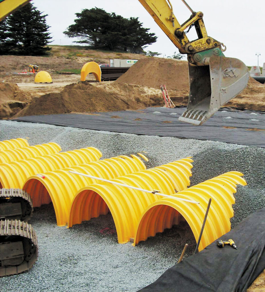
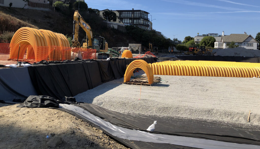
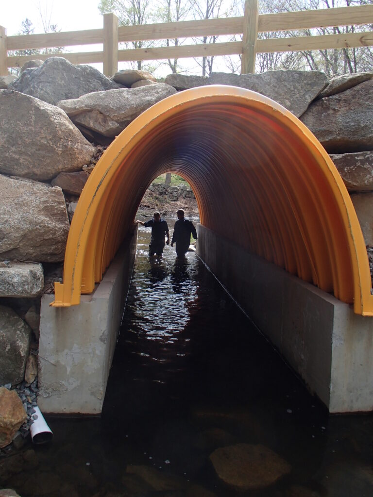
One example of such a solution sees attenuation systems located beneath a building, within its foundations. This can be a good option on tight urban sites where there is insufficient space for green SuDS on the surface or for below-ground attenuation outside the building footprint.
However, this is by no means an everyday arrangement and there are various issues to be considered when designing and installing such a system. These include the type of foundation structure used, how the various elements of the attenuation system will be installed, the possible presence and impact of groundwater and how the system will be inspected and maintained once the building is in operation.
Ideal applications
Below-structure attenuation systems are most commonly installed in buildings where the lowest level is dedicated to parking. These are typically mixed-use developments containing some combination of office, retail and residential space.
With parking space on the level directly above it, access to the attenuation system is far easier. This allows for critical inspection and maintenance activities to help achieve the maximum service life of the system.
When considering installing an attenuation system beneath a building with parking on its lower levels, it is likely that the underlying soils have already been evaluated for suitability with respect to the structure’s foundation system and the required minimum bearing capacity. This means that there will be reasonable information and knowledge about the soil type and groundwater situation.

It should be noted that any attenuation system should be installed above the seasonal high groundwater table, even if buoyant conditions can be managed. This practice allows for safe system access for inspection and maintenance.
Another important point is that no loads from the building’s foundations – such as piers, columns, footings or structural walls – should be transferred onto the attenuation system. That means that they cannot be installed under a mat or raft foundation system where a continuous slab will transfer weight to the underlying soil.
This rule applies even if the loading from foundations would be minimal. Products that are flexible have been designed to slightly change shape in order to transfer loads to the surrounding or underlying soil. This behaviour could adversely affect the support and stability of the structure’s foundation.
Product specifications
There are no standard specifications for implementing stormwater attenuation systems below buildings. However, systems placed below a structure must not adversely affect that structure and – as explained above – no structural loading should be transferred from the building to the attenuation system.

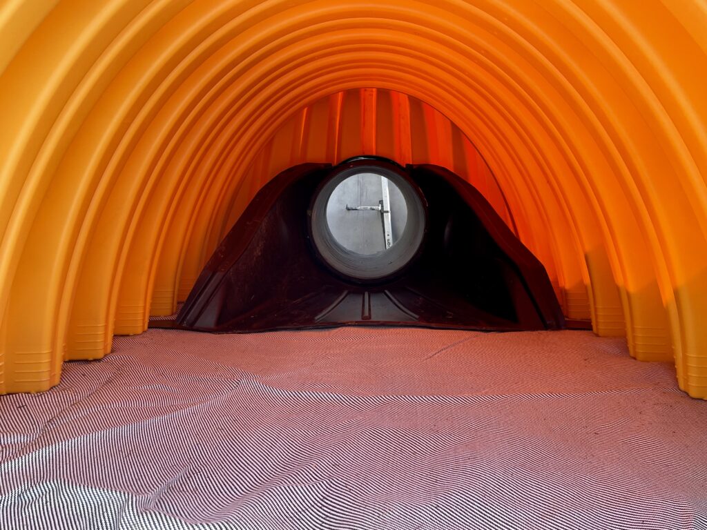
To facilitate ease of access, inspection and maintenance, pipe manifolds and connections are recommended to conform to minimum sizes detailed in BS EN 752 and BS EN 16933-1. In terms of storm sewer pipes, British Plastics Federation Pipes Group publication Specifications for plastic pipes, chambers, manholes and covers for drainage and sewerage applications is recommended reading.
Some manufacturers may be able to provide guidance and technical advice on placing attenuation systems below buildings. For instance, Advance Drainage Systems provides guidance on how to use its StormTech system below buildings in its technical note TN 6.24 Best Practices for Under-Structure Attenuation Systems. Any of the current StormTech chamber offerings are suitable for use below parking structures, subject to appropriate design and installation.
To line or not to line
Depending on the soil type and groundwater conditions of the site, a liner may be required to create a fully contained attenuation system with zero infiltration or exfiltration. The use of a liner prevents water infiltration into the underlying soils and stops it from coming into contact with the surrounding foundation system.
Liners are typically polyvinyl chloride (PVC), linear low-density polyethylene (LLDPE), ethylene propylene diene terpolymer (EPDM) or geosynthetic clay liners (GCLs). The product manufacturers should be consulted for guidance on the most appropriate liner solution.
In some circumstances, a liner is not necessary. Analysis by the project’s geotechnical and structural engineers will help determine this by looking at the impact that water will have on the soils and on the foundation system.
The project geotechnical engineer should review the soil conditions to determine whether moisture-sensitive native soils are at or below the system elevation. The project structural engineer should evaluate the foundation system specified to determine whether water will adversely affect the system and determine if waterproofing is required.
If the structural and geotechnical engineers determine that a liner is not required, a non-woven geotextile is recommended to minimise the migration of soil into the attenuation system’s structural backfill.
Installation considerations
It is important to consider all the temporary loadings that could be applied to the attenuation system during the construction phase. Construction activities for foundation preparation and building erection increases the risk of excessive loading on the buried attenuation system. Practices like proof rolling to test the strength and uniformity of subbase material or loads exerted by temporary shoring may exceed the allowable loading on the attenuation product.
Phasing and proximity restrictions of construction vehicles, cranes, tower cranes, and temporary shoring, should be considered to ensure these activities do not place excessive load on the attenuation system. Systems such as StormTech that have been designed as standard to withstand loading from heavy good vehicles, including below car parks, can offer an advantage here. Prior to any activities or loads that fall outside of what is published in the manufacturer’s installation guide, the engineer and contractor should consult a representative to review loading and proximity to the attenuation system.
The positioning of the attenuation system is also crucial. The area where the system would be installed beneath a building is often tightly constrained and adequate spacing between the attenuation system and the foundation system is critical.
In addition to close supervision of the installation, an inspection regime should be carefully planned and executed. The attenuation system should be inspected during placement and backfill and then 30 days after installation to ensure that no damage has been incurred due to unplanned loading.
In conclusion
In the UK, the practice of locating stormwater attenuation systems directly below buildings is not common practice. However, with the right technical information and guidance, it can be a good way to reduce the impact of intense rainfall events and hence increase the resilience of the built environment around a planned development.