Monthly Archives: April 2023
A Case for Adoption
With Schedule 3 still over the horizon in England (if it happens at all), the Design and Construction Guidance for adoptable sewers covers minimum standards of design and construction of sewers. And recent changes to DCG give the green light to arch-shaped attenuation chambers – given certain criteria are met. Stuart Crisp, UK manager of Advanced Drainage Systems (ADS), reports.
Ofwat’s Design and Construction Guidance (DCG) for adoptable sewers remains the most important document defining minimum standards of design and construction of adoptable sewers in England, including certain SuDS components. It has been updated to include information about arch-shaped below-ground SuDS attenuation chambers. This makes it easier for water companies to adopt such drainage infrastructure.
Previously, there was no reference to arch-shaped attenuation structures in the DCG which has meant that it has been more difficult for water companies to adopt them. That all changes with the addition of this extra section.
The DCG first came into force on April 1st 2020, replacing the long-standing Sewers for Adoption guidance. Developers who design and install sewerage systems in line with the DCG can expect to have their systems adopted by their local water companies – although it should be noted that water companies must be involved at the earliest stages of design and specification to ensure that local requirements and nuances are met.
One of the notable things about the DCG is that it includes information on sustainable drainage systems (SuDS) and that the definition of a sewer has been broadened to include certain SuDS components. This means that water companies in England can adopt SuDS components under Section 104 of the Water Industry Act 1991 which satisfy the requirements set out in DCG in the same way that they can adopt pipes, manholes and other sewerage infrastructure.
Version 2.2 of the DCG, first available through the Water UK website in November last year, identifies arch-shaped attenuation structures for the first time and requires that such systems can demonstrate full compliance with all the new requirements.
The relevant information can be found in section C7.8 of the document which covers Tanks, in clause C7.8.4d which says:
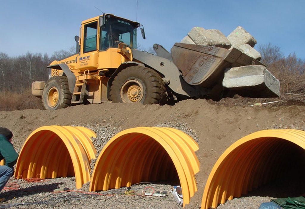
“d) where half pipe or arch structures are proposed, the design must (in addition to the above) demonstrate how the system can be cleaned/jetted and done so without damage or erosion of base materials or membrane. Further design evidence should outline how, in areas of a high-water table, groundwater is kept out of the system and, when positioned under highways, that the loading criteria is acceptable to both undertaker and adopting Highway Authority (if applicable).”
Any changes to the DCG must first be assessed and accepted by the Independent Sewerage Adoption Panel, which is made up of representatives from water companies and developers and then a recommendation made to Ofwat for their approval.
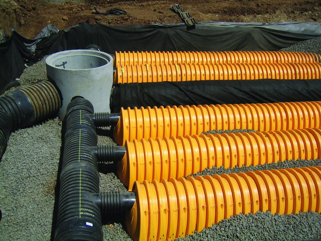
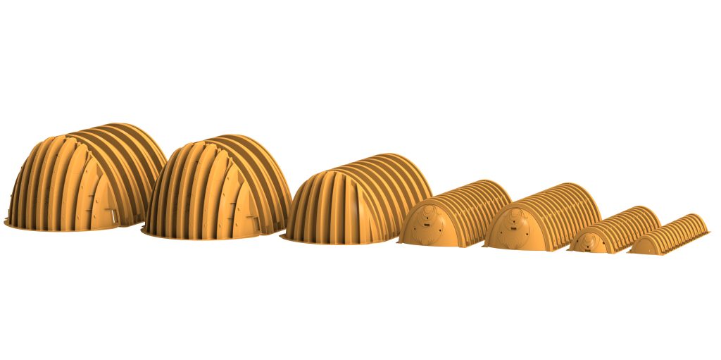
The inclusion of arch-shaped structures, such as ADS’s StormTech, has been initially well-received by water companies – and paves the way for developers to offer them without having to do additional work to prove their suitability.
For more information on Advanced Drainage Systems, visit www.adspipe.co.uk.