Monthly Archives: October 2025
Grey SuDS: exploring proprietary attenuation options
Stuart Crisp, UK Manager, Advanced Drainage Systems, looks at the range of proprietary attenuation solutions available for ‘grey’ Sustainable Drainage Systems (SuDS), offering flexibility and performance when vegetative approaches are not practical or sufficient.
Permeable paving
Among the most commonly used proprietary solutions is permeable block paving, which allows water to pass through joints between blocks, filtering through coarse sand and then granular fill beneath. This provides two stages of treatment – filtration and adsorption/biodegradation. It tends to require less excavation than below ground tanks, but regular maintenance is critical to prevent clogging of the joints, whilst care must be taken to ensure that the ‘wash water’ does not enter the system. Water companies rarely adopt permeable paving as it also serves as structural pavement.
Geocellular crates
Crate-based systems can provide high storage volume within a limited footprint and are relatively easy to install. However, they are prone to sediment build-up and often lack adequate upstream treatment; full sediment removal from the tank can be difficult. This can reduce flow rates and storage capacity over time. Not all crates meet current structural standards, and some adopters may not accept them. The SuDS Manual recommends upsizing storage volume of “difficult to clean” systems by 10% to account for sediment accumulation.
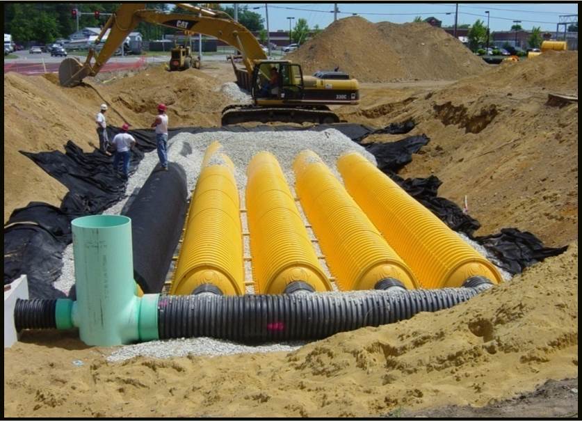
Large-diameter pipes
Used singly or in parallel, these are an established attenuation method. Typically made of concrete, steel or plastic, they can be cost-effective. However, their size and weight can increase transport and installation costs. Excavation requirements are usually greater, and some pipe types may not meet adoption criteria.
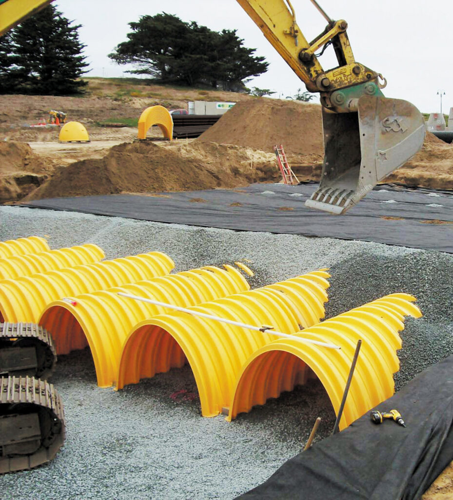
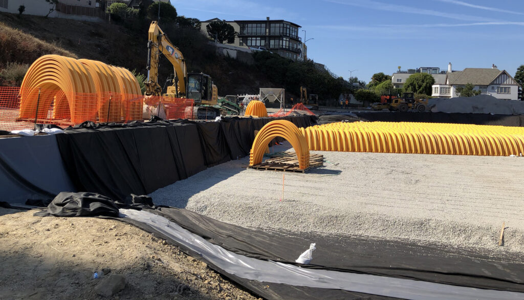
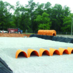
Arch-shaped chambers
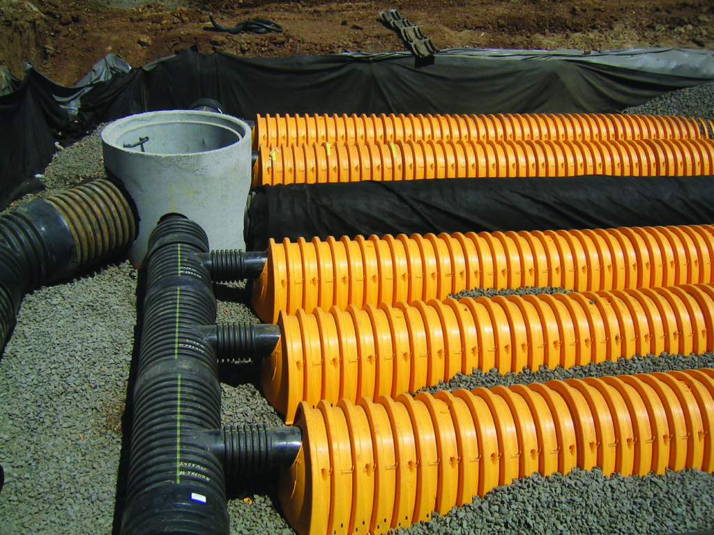
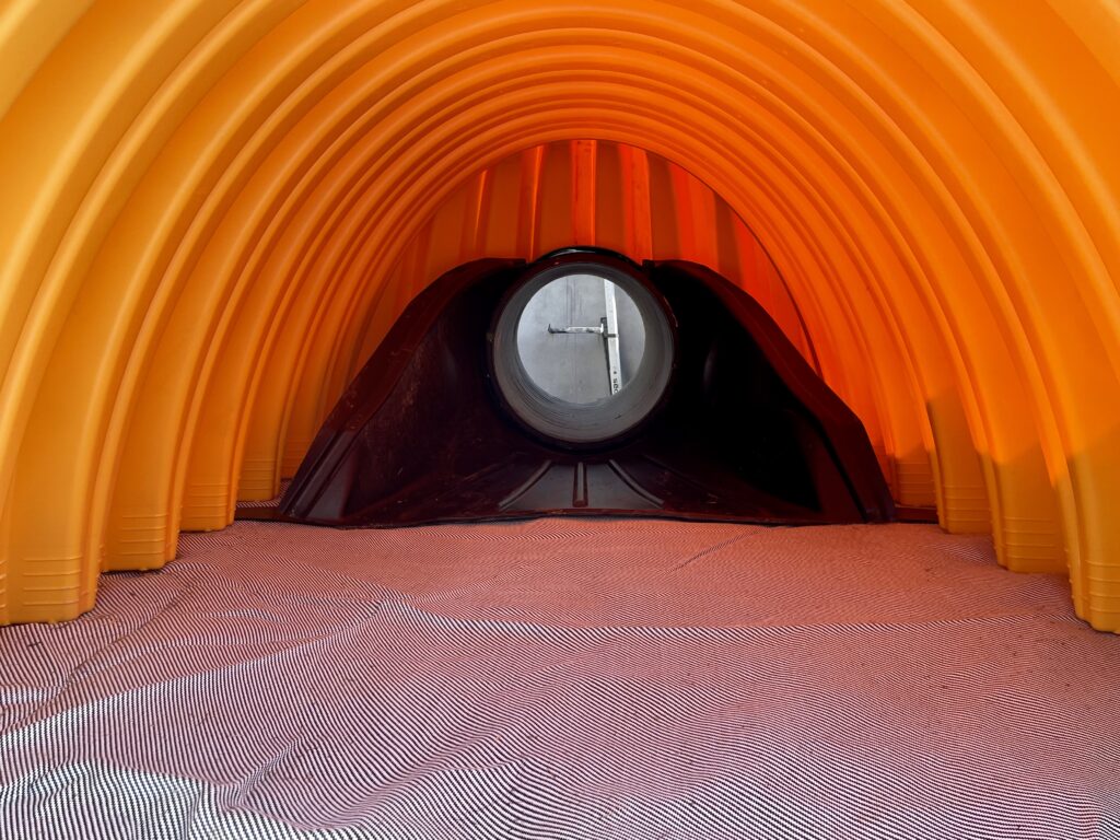
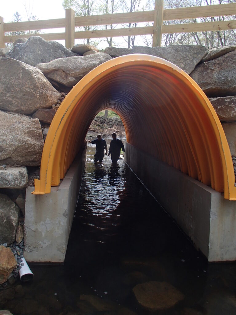
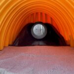
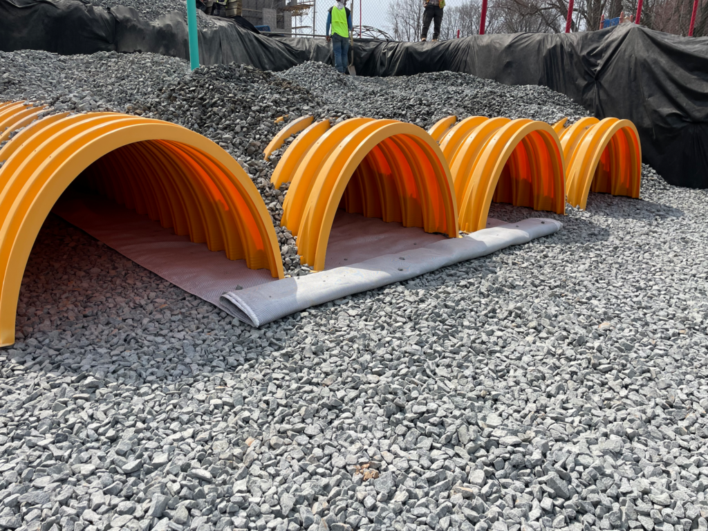
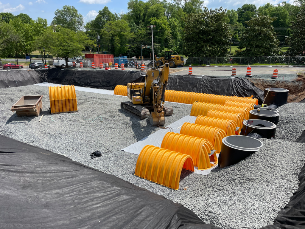
Innovative systems like arch-shaped chambers (e.g. StormTech) combine storage and treatment. Lightweight, modular and easy to install, they can be fitted around existing infrastructure and operate at shallow depths while supporting heavy loads. StormTech includes Isolator Row, a built-in treatment system that removes sediments and other pollutants– often eliminating the need for additional upstream treatment devices.
This brand of arches provides a total of four stages of water treatment: sedimentation and filtration in Isolator Row, followed by adsorption and biodegradation in the surrounding stone. It is compliant with the requirements set out in Design and Construction Guidance (DCG) for sewer adoption.
Green and grey
Vegetative SuDS (e.g. ponds, swales) can be effective where space is available and pollutant loads are low. But limiting designs to green features may compromise performance in certain situations. A hybrid approach – combining green and grey infrastructure may provide a lower cost, higher performing and lower environmental impact solution.
All SuDS systems require maintenance – natural ones included. Ponds need de-silting; vegetation must be managed; and litter removed. Similarly, proprietary systems must maintain hydraulic performance and treatment function. Substituting components purely to cut capital costs often risks long-term effectiveness.
With climate change increasing extreme rainfall events, and the associated sediment and pollutant loads, designers need flexible tools. Grey and green SuDS, used in combination, can deliver technically, environmentally and economically sustainable solutions for the lifetime of a development.
Under structure attenuation
Stuart Crisp, UK manager of Advanced Drainage Systems, considers best practices for under-structure attenuation systems.
Climate change is increasing the risk of flooding with all the negative impacts that such incidents bring to buildings, infrastructure and communities. The Environment Agency’s latest estimates show that while around 6.3 million properties in England are at risk of flooding today, this number could grow to 8 million by the middle of the century.
The need to consider resilience to climate change when designing our new buildings and developments is rightly moving up the agenda for authorities and for developers. Delivering resilience to flooding requires drainage engineers to deploy a whole toolbox of measures to help slow the flow of water from roofs and hard surfaces into sewers, to prevent them becoming overwhelmed during rainfall events. In some situations that can mean turning to less conventional solutions.
One example of such a solution sees attenuation systems located beneath a building, within its foundations. This can be a good option on tight urban sites where there is insufficient space for green SuDS on the surface or for below-ground attenuation outside the building footprint.
However, this is by no means an everyday arrangement and there are various issues to be considered when designing and installing such a system. These include the type of foundation structure used, how the various elements of the attenuation system will be installed, the possible presence and impact of groundwater and how the system will be inspected and maintained once the building is in operation.
Ideal applications
Below-structure attenuation systems are most commonly installed in buildings where the lowest level is dedicated to parking. These are typically mixed-use developments containing some combination of office, retail and residential space.
With parking space on the level directly above it, access to the attenuation system is far easier. This allows for critical inspection and maintenance activities to help achieve the maximum service life of the system.
When considering installing an attenuation system beneath a building with parking on its lower levels, it is likely that the underlying soils have already been evaluated for suitability with respect to the structure’s foundation system and the required minimum bearing capacity. This means that there will be reasonable information and knowledge about the soil type and groundwater situation.

It should be noted that any attenuation system should be installed above the seasonal high groundwater table, even if buoyant conditions can be managed. This practice allows for safe system access for inspection and maintenance.
Another important point is that no loads from the building’s foundations – such as piers, columns, footings or structural walls – should be transferred onto the attenuation system. That means that they cannot be installed under a mat or raft foundation system where a continuous slab will transfer weight to the underlying soil.
This rule applies even if the loading from foundations would be minimal. Products that are flexible have been designed to slightly change shape in order to transfer loads to the surrounding or underlying soil. This behaviour could adversely affect the support and stability of the structure’s foundation.
Product specifications
There are no standard specifications for implementing stormwater attenuation systems below buildings. However, systems placed below a structure must not adversely affect that structure and – as explained above – no structural loading should be transferred from the building to the attenuation system.

To facilitate ease of access, inspection and maintenance, pipe manifolds and connections are recommended to conform to minimum sizes detailed in BS EN 752 and BS EN 16933-1. In terms of storm sewer pipes, British Plastics Federation Pipes Group publication Specifications for plastic pipes, chambers, manholes and covers for drainage and sewerage applications is recommended reading.
Some manufacturers may be able to provide guidance and technical advice on placing attenuation systems below buildings. For instance, Advance Drainage Systems provides guidance on how to use its StormTech system below buildings in its technical note TN 6.24 Best Practices for Under-Structure Attenuation Systems. Any of the current StormTech chamber offerings are suitable for use below parking structures, subject to appropriate design and installation.
To line or not to line
Depending on the soil type and groundwater conditions of the site, a liner may be required to create a fully contained attenuation system with zero infiltration or exfiltration. The use of a liner prevents water infiltration into the underlying soils and stops it from coming into contact with the surrounding foundation system.
Liners are typically polyvinyl chloride (PVC), linear low-density polyethylene (LLDPE), ethylene propylene diene terpolymer (EPDM) or geosynthetic clay liners (GCLs). The product manufacturers should be consulted for guidance on the most appropriate liner solution.
In some circumstances, a liner is not necessary. Analysis by the project’s geotechnical and structural engineers will help determine this by looking at the impact that water will have on the soils and on the foundation system.
The project geotechnical engineer should review the soil conditions to determine whether moisture-sensitive native soils are at or below the system elevation. The project structural engineer should evaluate the foundation system specified to determine whether water will adversely affect the system and determine if waterproofing is required.
If the structural and geotechnical engineers determine that a liner is not required, a non-woven geotextile is recommended to minimise the migration of soil into the attenuation system’s structural backfill.
Installation considerations
It is important to consider all the temporary loadings that could be applied to the attenuation system during the construction phase. Construction activities for foundation preparation and building erection increases the risk of excessive loading on the buried attenuation system. Practices like proof rolling to test the strength and uniformity of subbase material or loads exerted by temporary shoring may exceed the allowable loading on the attenuation product.
Phasing and proximity restrictions of construction vehicles, cranes, tower cranes, and temporary shoring, should be considered to ensure these activities do not place excessive load on the attenuation system. Systems such as StormTech that have been designed as standard to withstand loading from heavy good vehicles, including below car parks, can offer an advantage here. Prior to any activities or loads that fall outside of what is published in the manufacturer’s installation guide, the engineer and contractor should consult a representative to review loading and proximity to the attenuation system.
The positioning of the attenuation system is also crucial. The area where the system would be installed beneath a building is often tightly constrained and adequate spacing between the attenuation system and the foundation system is critical.
In addition to close supervision of the installation, an inspection regime should be carefully planned and executed. The attenuation system should be inspected during placement and backfill and then 30 days after installation to ensure that no damage has been incurred due to unplanned loading.
In conclusion
In the UK, the practice of locating stormwater attenuation systems directly below buildings is not common practice. However, with the right technical information and guidance, it can be a good way to reduce the impact of intense rainfall events and hence increase the resilience of the built environment around a planned development.
Designing for water quality using mitigation indices
Stuart Crisp, UK manager at Advanced Drainage Systems (ADS), looks at verified mitigation indices for engineered SuDS components
The drive to improve water quality has gained momentum in recent years, reinforced by the Government’s Plan for Water, published by Defra in April 2023. It highlights the urgent need to address water pollution, with Sustainable Drainage Systems (SuDS) recognised as a key part of the solution. While SuDS are often associated with managing water quantity – reducing runoff and flows into sewers and minimising combined sewer overflow discharges – they also play a vital role in improving water quality by removing pollutants from surface water.
In practice, the water quality element is sometimes overlooked, down-specified or cut in so-called ‘value engineering’ exercises, where the hydraulic aspects are the key focus to manage flood prevention and other aspects, such as maintenance, are downplayed short shrift. Effective SuDS design requires a risk-based approach that accounts for both water quantity and quality, deploying a management train of natural and engineered SuDS components tailored to the types and levels of pollution present.
The CIRIA SuDS Manual (C753) sets out a framework for this approach. It introduces pollution hazard indices for different land uses and pollutants – total suspended solids (TSS), metals, and hydrocarbons. For example, a public car park might have indices of 0.7 for TSS, 0.6 for metals, and 0.7 for hydrocarbons. Designers must then identify SuDS components that, alone or in combination, achieve sufficient mitigation indices to address these risks.
Natural SuDS elements such as swales and ponds have well-documented mitigation indices in the Manual. However, for engineered or proprietary components, performance data must be independently verified.
To bridge this gap, British Water has taken a leading role. In 2016, it published a Code of Practice for the Assessment of Manufactured Treatment Devices Designed to Treat Surface Run-off, followed in 2022 by a practical guide, Applying the CIRIA SuDS Manual (C753) Simple Index Approach to Proprietary/ Manufactured Stormwater Treatment Devices.

These provide a method for determining mitigation indices for engineered SuDS components. Manufacturers can test their products and publish independently verified data. Some manufacturers have their components listed on British Water’s publicly available database. This transparency and consistent approach helps designers and specifiers incorporate manufactured solutions into SuDS trains with confidence. One such example is the ADS StormTech combined attenuation and treatment system, often eliminating the need for additional SuDS treatment components.
Understanding the types of pollutants in surface runoff is central to effective design. Sediments are particularly important in water quantity and water quality management, reducing both the storage capacity and flow rate of SuDS elements and carrying pollutants attached to them, if not managed properly.

Metals are common in UK run-off and harmful to aquatic ecosystems at high concentrations. Hydrocarbons are another threat, exacerbated by changing rainfall patterns which wash accumulated pollutants into drains during intense storm events. Nutrient pollution, typically nitrogen and phosphorus from agriculture or sewer outfalls, can trigger algal blooms, depleting oxygen in water bodies and damaging aquatic life.
SuDS that manage these pollutants requires more than simply meeting regulatory standards. Sediment management, for example, should be planned from the outset, with maintenance regimes ensuring long-term performance. By adopting a holistic, risk-based strategy for water quantity and quality and using both natural and verified engineered components, designers can deliver systems that genuinely improve water quality.
Porosity of structural embedment for below-ground attenuation systems
Stuart Crisp, UK manager of Advanced Drainage Systems (ADS) looks at how the porosity of structural backfill around arch-shaped attenuation chambers relates to storage volume, design and calculation.
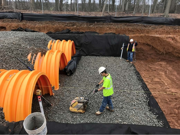
In subsurface stormwater management systems, selecting the right embedment material is critical to balancing structural integrity with hydraulic capacity. For example, arch-shaped chambers, such as ADS StormTech, recommend that clean, single-sized, angular aggregate conforming to BS EN 13242 grade 20/40 is used in the zones surrounding its chambers and has a porosity value of 40%.This makes the attenuation system more efficient as it enables additional storm water to be stored within the voids of the stone.
This value is based on empirical data and installation practices, and it is essential for accurate storage volume calculations and long-term system performance.
Definition of porosity
Porosity (n) is defined as the percentage of void (empty) space within a material relative to its total volume. It is calculated using the formula: n = (Vv / Vt) × 100%, where Vv is the volume of voids and Vt is the total volume.
Related but distinct is the void ratio (e), expressed as a decimal: e = Vv / Vs, where Vs is the volume of solids. While often used in geotechnical engineering, void ratio should not be confused with porosity in hydraulic design applications. An embedment with a void ratio of 40% would not provide the required 40% porosity.
Why 40%?
Clean, single-sized, angular stone aggregate for foundation and embedment material inherently exhibits high porosity due to the absence of fine particles that would otherwise fill the voids between larger stones. StormTech arch-shaped attenuation chamber installation guidelines differentiate porosity between compacted and non-compacted conditions.
The foundation layer is compacted to ensure structural stability beneath the arch-shaped chamber. Aggregate placed in the embedment zone, which surrounds the sides and top of the chambers, is typically dumped and left uncompacted to avoid damaging the chambers. This looser placement yields average porosities above 45%.
While compaction can reduce porosity slightly, the difference is mitigated by the installation method. In practice, compacted bedding material still maintains an average porosity of approximately 40% based on laboratory and field test data. Since the embedment stone is not compacted, it generally has a greater porosity, and when averaged across both zones, the overall system porosity exceeds 40% making it a conservative and reliable value for design purposes.
Protection against soil migration
To maintain porosity and prevent soil fines from infiltrating and clogging the void space, arch-shaped attenuation chamber infiltration systems are encapsulated in a non-woven geotextile fabric. This geotextile acts as a barrier to soil migration while allowing water to pass through.
Using a 40% porosity for structural aggregate in arch-shaped chamber systems, such as StormTech, is both conservative and well-supported by rigorous testing. Designers can confidently apply this value in storage volume calculations, ensuring structural integrity and storage efficiency.
Further details can be found in ADS’s Technical Note 6.30, available at https://adspipe.co.uk/resources/