Category Archives: Engineering Features


Grey SuDS: exploring proprietary attenuation options

Stuart Crisp, UK Manager, Advanced Drainage Systems, looks at the range of proprietary attenuation solutions available for ‘grey’ Sustainable Drainage Systems (SuDS), offering flexibility and performance when vegetative approaches are not practical or sufficient.

Permeable paving

Among the most commonly used proprietary solutions is permeable block paving, which allows water to pass through joints between blocks, filtering through coarse sand and then granular fill beneath. This provides two stages of treatment – filtration and adsorption/biodegradation. It tends to require less excavation than below ground tanks, but regular maintenance is critical to prevent clogging of the joints, whilst care must be taken to ensure that the ‘wash water’ does not enter the system. Water companies rarely adopt permeable paving as it also serves as structural pavement.

Geocellular crates

Crate-based systems can provide high storage volume within a limited footprint and are relatively easy to install. However, they are prone to sediment build-up and often lack adequate upstream treatment; full sediment removal from the tank can be difficult. This can reduce flow rates and storage capacity over time. Not all crates meet current structural standards, and some adopters may not accept them. The SuDS Manual recommends upsizing storage volume of “difficult to clean” systems by 10% to account for sediment accumulation.

Large-diameter pipes

Used singly or in parallel, these are an established attenuation method. Typically made of concrete, steel or plastic, they can be cost-effective. However, their size and weight can increase transport and installation costs. Excavation requirements are usually greater, and some pipe types may not meet adoption criteria.

Arch-shaped chambers

Innovative systems like arch-shaped chambers (e.g. StormTech) combine storage and treatment. Lightweight, modular and easy to install, they can be fitted around existing infrastructure and operate at shallow depths while supporting heavy loads. StormTech includes Isolator Row, a built-in treatment system that removes sediments and other pollutants– often eliminating the need for additional upstream treatment devices.

This brand of arches provides a total of four stages of water treatment: sedimentation and filtration in Isolator Row, followed by adsorption and biodegradation in the surrounding stone. It is compliant with the requirements set out in Design and Construction Guidance (DCG) for sewer adoption.

Green and grey

Vegetative SuDS (e.g. ponds, swales) can be effective where space is available and pollutant loads are low. But limiting designs to green features may compromise performance in certain situations. A hybrid approach – combining green and grey infrastructure may provide a lower cost, higher performing and lower environmental impact solution.

All SuDS systems require maintenance – natural ones included. Ponds need de-silting; vegetation must be managed; and litter removed. Similarly, proprietary systems must maintain hydraulic performance and treatment function. Substituting components purely to cut capital costs often risks long-term effectiveness.

With climate change increasing extreme rainfall events, and the associated sediment and pollutant loads, designers need flexible tools. Grey and green SuDS, used in combination, can deliver technically, environmentally and economically sustainable solutions for the lifetime of a development.

New Civil Engineer - November 2025

Under structure attenuation

Stuart Crisp, UK manager of Advanced Drainage Systems, considers best practices for under-structure attenuation systems.

Climate change is increasing the risk of flooding with all the negative impacts that such incidents bring to buildings, infrastructure and communities. The Environment Agency’s latest estimates show that while around 6.3 million properties in England are at risk of flooding today, this number could grow to 8 million by the middle of the century.

The need to consider resilience to climate change when designing our new buildings and developments is rightly moving up the agenda for authorities and for developers. Delivering resilience to flooding requires drainage engineers to deploy a whole toolbox of measures to help slow the flow of water from roofs and hard surfaces into sewers, to prevent them becoming overwhelmed during rainfall events. In some situations that can mean turning to less conventional solutions.

One example of such a solution sees attenuation systems located beneath a building, within its foundations. This can be a good option on tight urban sites where there is insufficient space for green SuDS on the surface or for below-ground attenuation outside the building footprint.

However, this is by no means an everyday arrangement and there are various issues to be considered when designing and installing such a system. These include the type of foundation structure used, how the various elements of the attenuation system will be installed, the possible presence and impact of groundwater and how the system will be inspected and maintained once the building is in operation.

Ideal applications

Below-structure attenuation systems are most commonly installed in buildings where the lowest level is dedicated to parking. These are typically mixed-use developments containing some combination of office, retail and residential space.

With parking space on the level directly above it, access to the attenuation system is far easier. This allows for critical inspection and maintenance activities to help achieve the maximum service life of the system.

When considering installing an attenuation system beneath a building with parking on its lower levels, it is likely that the underlying soils have already been evaluated for suitability with respect to the structure’s foundation system and the required minimum bearing capacity. This means that there will be reasonable information and knowledge about the soil type and groundwater situation.

It should be noted that any attenuation system should be installed above the seasonal high groundwater table, even if buoyant conditions can be managed. This practice allows for safe system access for inspection and maintenance.

Another important point is that no loads from the building’s foundations – such as piers, columns, footings or structural walls – should be transferred onto the attenuation system. That means that they cannot be installed under a mat or raft foundation system where a continuous slab will transfer weight to the underlying soil.

This rule applies even if the loading from foundations would be minimal. Products that are flexible have been designed to slightly change shape in order to transfer loads to the surrounding or underlying soil. This behaviour could adversely affect the support and stability of the structure’s foundation.

Product specifications

There are no standard specifications for implementing stormwater attenuation systems below buildings. However, systems placed below a structure must not adversely affect that structure and – as explained above – no structural loading should be transferred from the building to the attenuation system.

To facilitate ease of access, inspection and maintenance, pipe manifolds and connections are recommended to conform to minimum sizes detailed in BS EN 752 and BS EN 16933-1. In terms of storm sewer pipes, British Plastics Federation Pipes Group publication Specifications for plastic pipes, chambers, manholes and covers for drainage and sewerage applications is recommended reading.

Some manufacturers may be able to provide guidance and technical advice on placing attenuation systems below buildings. For instance, Advance Drainage Systems provides guidance on how to use its StormTech system below buildings in its technical note TN 6.24 Best Practices for Under-Structure Attenuation Systems. Any of the current StormTech chamber offerings are suitable for use below parking structures, subject to appropriate design and installation.

To line or not to line

Depending on the soil type and groundwater conditions of the site, a liner may be required to create a fully contained attenuation system with zero infiltration or exfiltration. The use of a liner prevents water infiltration into the underlying soils and stops it from coming into contact with the surrounding foundation system.

Liners are typically polyvinyl chloride (PVC), linear low-density polyethylene (LLDPE), ethylene propylene diene terpolymer (EPDM) or geosynthetic clay liners (GCLs). The product manufacturers should be consulted for guidance on the most appropriate liner solution.

In some circumstances, a liner is not necessary. Analysis by the project’s geotechnical and structural engineers will help determine this by looking at the impact that water will have on the soils and on the foundation system.

The project geotechnical engineer should review the soil conditions to determine whether moisture-sensitive native soils are at or below the system elevation. The project structural engineer should evaluate the foundation system specified to determine whether water will adversely affect the system and determine if waterproofing is required.

If the structural and geotechnical engineers determine that a liner is not required, a non-woven geotextile is recommended to minimise the migration of soil into the attenuation system’s structural backfill.

Installation considerations

It is important to consider all the temporary loadings that could be applied to the attenuation system during the construction phase. Construction activities for foundation preparation and building erection increases the risk of excessive loading on the buried attenuation system. Practices like proof rolling to test the strength and uniformity of subbase material or loads exerted by temporary shoring may exceed the allowable loading on the attenuation product.

Phasing and proximity restrictions of construction vehicles, cranes, tower cranes, and temporary shoring, should be considered to ensure these activities do not place excessive load on the attenuation system. Systems such as StormTech that have been designed as standard to withstand loading from heavy good vehicles, including below car parks, can offer an advantage here. Prior to any activities or loads that fall outside of what is published in the manufacturer’s installation guide, the engineer and contractor should consult a representative to review loading and proximity to the attenuation system.

The positioning of the attenuation system is also crucial. The area where the system would be installed beneath a building is often tightly constrained and adequate spacing between the attenuation system and the foundation system is critical.

In addition to close supervision of the installation, an inspection regime should be carefully planned and executed. The attenuation system should be inspected during placement and backfill and then 30 days after installation to ensure that no damage has been incurred due to unplanned loading.

In conclusion

In the UK, the practice of locating stormwater attenuation systems directly below buildings is not common practice. However, with the right technical information and guidance, it can be a good way to reduce the impact of intense rainfall events and hence increase the resilience of the built environment around a planned development.

Drain Trader - October 2025

Designing for water quality using mitigation indices

Stuart Crisp, UK manager at Advanced Drainage Systems (ADS), looks at verified mitigation indices for engineered SuDS components

The drive to improve water quality has gained momentum in recent years, reinforced by the Government’s Plan for Water, published by Defra in April 2023. It highlights the urgent need to address water pollution, with Sustainable Drainage Systems (SuDS) recognised as a key part of the solution. While SuDS are often associated with managing water quantity – reducing runoff and flows into sewers and minimising combined sewer overflow discharges – they also play a vital role in improving water quality by removing pollutants from surface water.

In practice, the water quality element is sometimes overlooked, down-specified or cut in so-called ‘value engineering’ exercises, where the hydraulic aspects are the key focus to manage flood prevention and other aspects, such as maintenance, are downplayed short shrift. Effective SuDS design requires a risk-based approach that accounts for both water quantity and quality, deploying a management train of natural and engineered SuDS components tailored to the types and levels of pollution present.

The CIRIA SuDS Manual (C753) sets out a framework for this approach. It introduces pollution hazard indices for different land uses and pollutants – total suspended solids (TSS), metals, and hydrocarbons. For example, a public car park might have indices of 0.7 for TSS, 0.6 for metals, and 0.7 for hydrocarbons. Designers must then identify SuDS components that, alone or in combination, achieve sufficient mitigation indices to address these risks.

Natural SuDS elements such as swales and ponds have well-documented mitigation indices in the Manual. However, for engineered or proprietary components, performance data must be independently verified.

To bridge this gap, British Water has taken a leading role. In 2016, it published a Code of Practice for the Assessment of Manufactured Treatment Devices Designed to Treat Surface Run-off, followed in 2022 by a practical guide, Applying the CIRIA SuDS Manual (C753) Simple Index Approach to Proprietary/ Manufactured Stormwater Treatment Devices.

These provide a method for determining mitigation indices for engineered SuDS components. Manufacturers can test their products and publish independently verified data.  Some manufacturers have their components listed on British Water’s publicly available database. This transparency and consistent approach helps designers and specifiers incorporate manufactured solutions into SuDS trains with confidence. One such example is the ADS StormTech combined attenuation and treatment system, often eliminating the need for additional SuDS treatment components.

Understanding the types of pollutants in surface runoff is central to effective design. Sediments are particularly important in water quantity and water quality management, reducing both the storage capacity and flow rate of SuDS elements and carrying pollutants attached to them, if not managed properly.

Metals are common in UK run-off and harmful to aquatic ecosystems at high concentrations. Hydrocarbons are another threat, exacerbated by changing rainfall patterns which wash accumulated pollutants into drains during intense storm events. Nutrient pollution, typically nitrogen and phosphorus from agriculture or sewer outfalls, can trigger algal blooms, depleting oxygen in water bodies and damaging aquatic life.

SuDS that manage these pollutants requires more than simply meeting regulatory standards. Sediment management, for example, should be planned from the outset, with maintenance regimes ensuring long-term performance. By adopting a holistic, risk-based strategy for water quantity and quality and using both natural and verified engineered components, designers can deliver systems that genuinely improve water quality.

New Civil Engineer - October 2025

Porosity of structural embedment for below-ground attenuation systems

Stuart Crisp, UK manager of Advanced Drainage Systems (ADS) looks at how the porosity of structural backfill around arch-shaped attenuation chambers relates to storage volume, design and calculation.

In subsurface stormwater management systems, selecting the right embedment material is critical to balancing structural integrity with hydraulic capacity. For example, arch-shaped chambers, such as ADS StormTech, recommend that clean, single-sized, angular aggregate conforming to BS EN 13242 grade 20/40 is used in the zones surrounding its chambers and has a porosity value of 40%.This makes the attenuation system more efficient as it enables additional storm water to be stored within the voids of the stone.

This value is based on empirical data and installation practices, and it is essential for accurate storage volume calculations and long-term system performance.

Definition of porosity

Porosity (n) is defined as the percentage of void (empty) space within a material relative to its total volume. It is calculated using the formula: n = (Vv / Vt) × 100%, where Vv is the volume of voids and Vt is the total volume.

Related but distinct is the void ratio (e), expressed as a decimal: e = Vv / Vs, where Vs is the volume of solids. While often used in geotechnical engineering, void ratio should not be confused with porosity in hydraulic design applications. An embedment with a void ratio of 40% would not provide the required 40% porosity.

Why 40%?

Clean, single-sized, angular stone aggregate for foundation and embedment material inherently exhibits high porosity due to the absence of fine particles that would otherwise fill the voids between larger stones. StormTech arch-shaped attenuation chamber installation guidelines differentiate porosity between compacted and non-compacted conditions.

The foundation layer is compacted to ensure structural stability beneath the arch-shaped chamber. Aggregate placed in the embedment zone, which surrounds the sides and top of the chambers, is typically dumped and left uncompacted to avoid damaging the chambers. This looser placement yields average porosities above 45%.

While compaction can reduce porosity slightly, the difference is mitigated by the installation method. In practice, compacted bedding material still maintains an average porosity of approximately 40% based on laboratory and field test data. Since the embedment stone is not compacted, it generally has a greater porosity, and when averaged across both zones, the overall system porosity exceeds 40% making it a conservative and reliable value for design purposes.

Protection against soil migration

To maintain porosity and prevent soil fines from infiltrating and clogging the void space, arch-shaped attenuation chamber infiltration systems are encapsulated in a non-woven geotextile fabric. This geotextile acts as a barrier to soil migration while allowing water to pass through.

Using a 40% porosity for structural aggregate in arch-shaped chamber systems, such as StormTech, is both conservative and well-supported by rigorous testing. Designers can confidently apply this value in storage volume calculations, ensuring structural integrity and storage efficiency.

Further details can be found in ADS’s Technical Note 6.30, available at https://adspipe.co.uk/resources/

NCE - August 2025

Stormwater attenuation systems made easy with the StormTech Design Tool

Advanced Drainage Systems (ADS), a global leader in corrugated thermoplastic drainage pipes and a specialist in water management systems; has launched an enhanced version of its StormTech Design Tool which allows engineers, designers and other users to quickly and easily generate optimised stormwater attenuation systems that integrate with CAD and other design, engineering, specification and submittal documents. 

The StormTech Design Tool is fast, easy and free to use and allows the user to generate quick layouts, import site plans and maps, customise layouts, and save, manage, revise them. It also provides for multi-bed design systems. Resulting drawings are compatible with AutoCAD 2013 and above.

Now with clearer messaging and faster formatting, the StormTech Design Tool also provides a schedule of materials as part of the design output, so estimates can be prepared in minutes.

Simply set up a free account and upload a site plan or map from a pdf or image file. Enter the required hydraulic criteria, system parameters and select a chamber size and the StormTech Design Tool will automatically build an optimised system.

The StormTech Design Tool allows toggling between pipe and chamber sizes; and scaling, rotating or moving the StormTech bed to meet the project requirements. The tool can cater for multi-bed sites, interior inlets and direct input manifolds; and individual chambers, structures and manifolds can be added or removed.

ADS UK has developed a quick guide to assist first-time users of the design tool. It can be found at https://adspipe.co.uk/stormtech-design-tool-quick-guide/. ADS offers comprehensive technical support for design, installation and maintenance; as well as training and CPDs on below ground attenuation covering legislation, best practice and comparable systems.

Drain Trader - July 2025

Attenuation below buildings

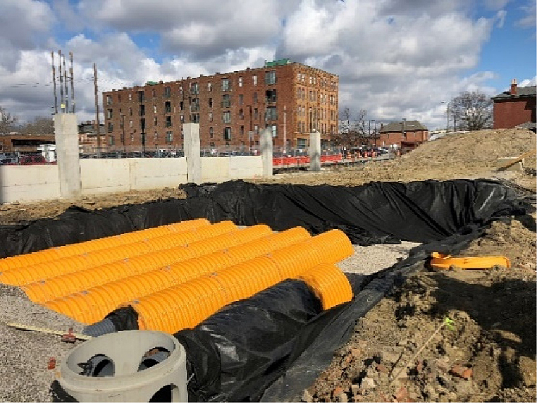
It is possible to store stormwater in attenuation structures below buildings–but there are important considerations for the design engineer, says Stuart Crisp, UK manager of Advanced Drainage Systems.

In dense urban areas, such as sites where a new building covers the entire footprint of the development plot, it may make sense to install SuDS attenuation assets below the building itself. However, during optioneering, there are multiple factors that the designer should consider including the foundation design, construction sequencing, ground conditions, level of the water table and how the system will be inspected andmaintained.

This arrangement is most often deployed below multi-storey buildings, such as offices, residential or mixed use, where the lower level is dedicated to parking. This allows for easy access to the below-ground attenuation system so that regular inspections and maintenance interventions can take place, maximising the service life of the system.

When initially assessing whether below-building attenuation might be possible, the first requirement is that no loading from the building should be transferred to the attenuation asset. Attenuation assets should not be installed under buildings with a mat or raft foundation system as a continuous slab would transfer weight to the underlying soil and hence onto the attenuation device.

Geo-technical and structural engineers should also investigate the soil conditions to determine whether the ground around the attenuation asset is moisture sensitive and whether water would adversely affect the building’s foundation systems. It may be necessary for the attenuation device to be contained, for instance with a thermoplastic liner, to prevent water infiltrating into the underlying soils or contacting the surrounding foundation system.

Another important consideration is the position of the ground water table, throughout the year. Even if buoyant conditions can be managed, it is not recommended that below-building attenuation systems are installed below the level of the seasonal high groundwater table.

A designer should also consider temporary loading on the below-ground attenuation system during the construction phase. The phasing and proximity of heavy construction plant, mobile and tower cranes, form work and false work should be tightly controlled to ensure that loading on the buried attenuation system is not excessive.

As with all such installations, it is important to carry out regular inspections throughout the installation of the attenuation system. Ensuring that a system is installed in accordance with the design and with the manufacturer’s instructions is vital in assuring that the system will perform as intended. Depending on the footprint of the building and the sizing of the attenuation device, space around the perimeter of the installation may be limited, which could impact on the ability to inspect the installation.

In conclusion, installing attenuation assets below a building can be a good solution in limited situations. Given the potential cost and difficulty of replacing a system that has failed for whatever reason, it is more important than ever to assure the quality of the installation and to check that no damage has been caused through inadvertent overloading of the ground during construction.

New Civil Engineer - June 2025

SuDS and recycled aggregate

Using recycled aggregate for below ground stormwater attenuation systems can lead to environmental, planning and cost benefits. Stuart Crisp, UK Manager, Advanced Drainage Systems, talks us through the points to consider.

It is always worth considering whether recycled aggregate could be used in place of virgin aggregate for the construction of a new asset. As well as conserving natural resources for future generations, it can lead to cost savings and help reduce waste produced by construction and demolition projects.

Another reason to consider using recycled aggregate is a move towards circularity principles among certain clients and planning authorities. As well as finding ways to design out waste and extend the life of built assets, circularity considers how elements of a building or infrastructure can be reused, the aim being to redeploy materials for the highest value purpose possible.

Recycled aggregate can be used with below ground stormwater attenuation systems, which can be considered a higher value use than simply deploying them for general backfill. However, when using such aggregate, there are some additional considerations for the designer, specifier or installer, which this article will address. Specifiers need to be aware of the relevant standards, together with any technical
guidance from the manufacture of the attenuation product.

New policies

Reuse and recycling of materials has come into sharper focus recently with the introduction of new planning policies and corporate strategies. The Greater London Authority has taken a lead on this: from March 2022, its planning process has required developments over a certain size to submit Circularity Economy Statements.

A Circular Economy Statement should demonstrate how materials arising from demolition will be reused or recycled, consider resource efficiency in an asset’s design and construction and look at what will happen to the asset at end of life. Some developers are also homing in on circularity. Warehouse developer Prologis is showcasing circularity principles with projects such as the Prologis Park Waalwijk DC3 in Tarkett in the Netherlands. Closer to home, commercial property developer GPE announced in November last year that it was introducing a Circularity Score, aimed to reduce the quantities of virgin materials it uses in its development, with targets that will ramp up from 40% from April 2025 to over 50% by 2040.

Infrastructure owners are also working to include circularity principles in their construction and maintenance projects. In October 2024, the UK Water Partnership published a white paper on circularity in the water sector which references the need to reduce the use of virgin materials in construction.

This year National Highways will be developing performance and baselines for circularity. And by 2030, it will have integrated circularity assessments into its design and maintenance standards to look at the reduction of virgin materials, waste management and material flows.

Good track record

Compared to many of its European counterparts, the UK has a good track record on using recycled aggregate in construction. In its 2024 report, Construction Aggregates Supply in Great Britain, the Mineral Product Association (MPA) estimates that 66.1 million tonnes of construction, demolition and excavation waste (CDEW) was recycled in 2022, or 27% of the total aggregates supply.

However, the MPA does point out that more robust means of collecting data on CDEW is needed. Digital waste tracking, which is proposed to become mandatory from April 2025, would give a more accurate picture and help encourage more circularity, says the MPA.

Although recycled aggregate can be used for drainage, including for below-ground attenuation assets, they could be deployed far more often. Since sourcing the right type of recycled aggregate could require additional time and resource, it may not make sense for contractors to pursue this route.

Where recycled aggregate is to be used for below-ground drainage, standards and guidance is available. BS EN 13242 (+A1:2013) sets out the properties required for aggregates produced from natural, manufactured or recycled materials for hydraulically bound and unbound materials for civil engineering works. Recycled aggregate from a reputable supplier will be CE marked to demonstrate that it complies with the standard.

Additional guidance on the use of BS EN 13242 is contained in document PD 6682-6:2009+A1:2013, available from the British Standards Institution. This gives information on how to apply the standard in the UK.

The Quality Protocol ‘Aggregates from inert waste, ’published by the Waste Resource and Action Programme (WRAP) and the Environment Agency, provides information on demonstrating compliance of materials, together with good practice on storage, transportation and handling of recycled products. Note that this is currently under review, with a revised document being drafted.

Specifications for underground attenuation

Manufacturers of underground stormwater attenuation devices should provide technical guidance on specifying recycled aggregate for their systems. For instance, Advanced Drainage System’s StormTech arch-shaped attenuation system has a technical note on the subject which sets out specifications for gradation, angular or subangular classification, deleterious materials and freeze-thaw resistance.

A general specification for a StormTech installation with recycled aggregate would call for a 20/40 grade which is clean, crushed, angular, with less than 5% fines. The fines content is important because the aggregate around StormTech arches is performing a water storage function as well as a structural one.

If recycled concrete is to be used, tufa precipitate from unhydrated cement may be present. This could lead to the occlusion of separation fabrics or could block infiltration or exfiltration surfaces.

When specifying recycled aggregate, it may be necessary to ask for hardness and durability testing to ensure that it meets structural requirements. Again, a reputable supplier will provide certification and assurance that the aggregate meets the specification.

A further consideration is the chemical content, alkalinity and potential toxicity of the recycled aggregate, together with the composition of the ground into which it will go. For instance, if there are sulphites in the ground, they could attack recycled concrete, impacting on its performance over time.

For below-ground stormwater attenuation systems, the amount of aggregate, whether recycled or virgin, varies considerably depending on the type of system. Modular boxes, often referred to as crates, use relatively little aggregate, installed around the outer perimeter of the tank. Systems that deploy large-diameter pipes require a greater proportion of aggregate surrounding the entire external surface of the pipe. The total amount and type of aggregate required may vary between rigid pipes, such as concrete and flexible pipes, such as plastic.

With arch-shaped attenuation chambers, such as StormTech, considerably more aggregate in relation to the product is used. This is because the aggregate has a dual function: to provide additional storage volume which contributes to the efficiency of the system with respect to its water storage capacity; and to provide structural support.

The elliptical shape of the chambers forms the aggregate around it into arches and columns, transferring loads away from the chambers so that they can be installed at shallow and greater depths.

Manufacturers may provide design aids, such as StormTech’s Site ASSIST app which provides information on embedment material and construction methodology as well as detailed installation details in the form of drawings and animated videos. Apps such as this can also help ensure that the contractor installs the underground attenuation assets as intended.

Cost and carbon

Recycled aggregate can cost less than virgin aggregate, although this is not always the case. Cost tends be location dependent.

The price of virgin stone varies between quarries and will also be affected by the distance over which it must be transported. There are more quarries than aggregate recycling facilities which may mean that, if a construction site is close to a quarry, virgin aggregate is likely to be a more cost-effective option. However, for sites that are within a reasonable distance of a recycled aggregate supplier, there could be economica dvantages of swapping virgin for recycled aggregate.

When it comes to associated carbon emissions, recycled aggregate will not always come in with a smaller carbon footprint than virgin aggregate. Recycled aggregate requires more processing, including demolition, grading and transportation to a recycling facility. If that facility is further away than a local quarry, there will be more carbon emissions associated with transport too.

One factor that may offset the transport and processing carbon emissions in favour of recycled aggregates is the use of recycled concrete that has been stockpiled to enable the material to carbonate.

Simply put, this is a process that takes carbon dioxide from the atmosphere into the surface of the concrete where it reacts with the material to create calcium carbonate.

From a carbon perspective, it is worth considering that systems with a higher aggregate-to-product ratio tend to have a lower overall carbon footprint for the same storage volume than those with lower ones. This would include systems such as arch-shaped chambers, where the aggregate is used both structurally and to store water.

Clearly, there can be tensions between reducing embodied carbon emissions associated with the construction of new assets and the use of recycled products in order to conserve natural resources and reduce waste. These issues will be addressed as policies and sustainability strategies become more nuanced to include circularity considerations.

Drain Trader - June 2025

Why ‘install as per manufacturer’s instructions’ is not enough

A competent design for a buried drainage structure must encompass the performance of the product itself, the materials around it and all the interactions in that system, says Stuart Crisp, UK manager of Advanced Drainage Systems (ADS).

It is common to receive drawings for buried drainage structures which simply say ‘install as per manufacturer’s instructions.’ That’s a risky strategy which does not ensure that a SuDS or other drainage system will perform as the designer intended.

When considering the structural integrity of a buried drainage product, such as below-ground SuDS attenuation assets, the designer must consider the whole system: the performance of the product itself; the embedment material and how the product interacts with it; the subgrade material surrounding the excavation and its performance; and the loadings which will be applied.

Failure to appreciate all these elements can lead, in a worst-case scenario, to failure of that structure. For instance, CIRIA C737 structural and geo-technical design of modular geo-cellular drainage systems, provides a list of the main contributing factors to most failures of such structures. The first two are: insufficient appreciation of the importance of an appropriate structural and geo-technical design; and failure to consider particular ground conditions on the site or not allowing for deformation of theunits.

CIRIA C737 underlines the fact that a competent engineer should oversee the design and installation of geo-cellular tanks or crates. And it points out that the responsible engineer should be experienced in ground engineering.

For below-ground SuDS attenuation products, the design approach will be fundamentally different, depending on the type of product deployed, whether crate large-diameter pipe or arch-shaped structure. It is also important to note that systems based around pipes behave very differently,depending on what material the pipe is made of.BS 9295:2020 Guide to the structural design of buried pipes explains that the stiffness of the native soil surrounding a pipe can be particularly important for a flexible pipe, such as a plastic one. Flexible pipes deflect on loading into an oval shape and can develop significant lateral earth pressure around them. On the other hand, pipes made from rigid materials, such as concrete or clay, do not deflect and therefore take most of the loading themselves.

Below-ground attenuation crates are subject to lateral loading, as well as to loading from above. So, the designer must factor in the type of material around the product, as well as any loading due to the presence of groundwater.

For buried arch-shaped structures, the distribution of loading is different again. The arch shape concentrates the overburden loads through the embedment stone to the spaces between the feet of the arches. The loads are then transferred through a layer of foundation stone to the native subgrade beneath.

Manufacturers should provide technical guidance related to the loading and interactions of their products with the native soil. For instance, ADS’s technical note TN6.22 StormTech Subgrade Performance Considerations does this for arch-shaped chambers.

One of the risks with buried drainage structures is that design responsibilities between the client, designer and manufacturer are often unclear which can mean that the contractor is left to select a product without sufficient information. This risk can be mitigated by a more rigorous approach in the early stages of design.

New Civil Engineer - March 2025

Recycled aggregate and below-ground SuDS

Recycled aggregate could be used more frequently for installation of below-ground attenuation assets, says Stuart Crisp, UK manager of Advanced Drainage Systems(ADS).

Substituting recycled aggregate for virgin aggregate helps retain natural resources for future generations and can come with cost benefits. Although there is an opportunity to do this with below-ground attenuation assets in sustainable drainage systems (SuDS), contractors often choose to go with what they know–which is the ‘safe’ route of virgin aggregates.

In specifying recycled aggregates, designers and contractors should be aware of the relevant standards, together with any technical guidance from the manufacturer of the attenuation product. BS EN 13242 (+A1:2013) sets out the properties required for aggregates produced from natural, manufactured or recycled materials for hydraulically bound and unbound materials for civil engineering works. Reputable suppliers will provide recycled aggregate with a CE mark to demonstrate conformity to the standard.

Different product manufacturers may have additional requirements for recycled aggregate which is to be used in below-ground SuDS attenuation systems to ensure that it performs its intended functions. For instance, ADS Pipe’s technical guidance for recycled aggregate for its StormTech system calls for a 20/40mm aggregate which is clean, crushed and angular, with less than 5% fines. The reason for limiting fines is that the void space between the aggregate needs to be preserved to allow for the storage and movement of the water through the matrix of aggregate.

Specifications should set out an average porosity for the aggregate. Porosity is the volume of voids over the total volume; this is sometimes confused with void ratio which is the volume of voids over the volume of solids which can lead to installed systems not meeting design requirements.

Other factors to consider when selecting recycled aggregate include the nature of the ground and the ground water and whether there are any potentially aggressive substances present. Sulphites carried in ground water, for example, could react with recycled concrete aggregate and degrade it over time.

Different types of below-ground attenuation systems require different proportions of aggregate to manufactured product. Crates deploy small amounts of aggregate around their perimeter, large-diameter pipes and arch-shaped attenuation products use a greater proportion of aggregate.

With arch-shaped attenuation products, the aggregate around the arches has a dual purpose. It provides structural support, with the elliptical shape of the arches forming the aggregate around them into stone arches and structural columns, transferring the loads away from the chambers into the stiffer material surrounding them. The aggregate also provides additional storage volume which contributes to the efficiency of the attenuation system in terms of its water storage capability.

Recycled aggregate will not necessarily have lower embodied carbon than virgin aggregate, which tends to be supplied from quarries close to the point of installation.

Recycled aggregate can come at a lower cost than its virgin counterpart, again depending largely on transportation distances.

Generally speaking, attenuation products requiring a higher aggregate-to-product ratio tend to have a lower overall carbon footprint per cubic metre of storage than those requiring less aggregate-to-product.

Underground SuDS: derisking the future with standards, certifications and approvals

Anyone involved in the design, installation or adoption of below-ground SuDS attenuation assets should be doing their due diligence to ensure they are fit for purpose, says Stuart Crisp of ADS.

Below ground attenuation devices for sustainable drainage systems (SuDS), such as crates, are often considered a commodity. The tendency can be to fit the lowest cost option, given the volume of water required by the engineer’s design.

This may function very well on day one. But how can the ultimate asset owner be sure it will function as intended 10, 20 or more years down the line?

This is the question that any SuDS adopting body will be asking, when Schedule 3 of the Flood and Water Management Act 2010 comes into force in England, making SuDS for new developments mandatory. SABs must assess what maintenance and repair costs might be, in order to agree the commuted sum that a developer pays when handing over the asset.

An important part of the due diligence required for below ground SuDS attenuation devices is to check that the products selected meet all the necessary standards, certifications and approvals. To do that properly, it is important to deep dive into the detail of how manufacturers claim that their products comply.

Standards and certifications.

The starting point for any construction product to be used in the UK is that it must, bylaw, have a CE mark or a UKCA mark–although the date from which the UKCA mark will be required has recently been pushed back from June 2025 for at least two years. Next, products must conform to the relevant standards in terms of both functional performance-which is governed mainly by the evaluation, management and testing of the product’s material properties, manufacturing processes and dimensional tolerances–and the structural design process. These two distinct requirements can sometimes be found in two different standards or alternatively in separate parts of the same standard, depending on the product type and material.

British Standards (BS) are the most well known in the UK but in some cases, a harmonised standard, accepted by multiple nations, could apply, which would be designated BS EN or BS ISO in the UK. Note that there cannot be more than one standard covering the same scope in any territory.

For innovative solutions, where a product standard does not exist, manufacturers must take a different approach.

Some choose to cherry pick clauses from different standards in an attempt to demonstrate fitness for purpose, but this is not a reliable approach.

The responsible route is to put the product through an evaluation conducted by a recognised certification body such as the British Board of Agrément (BBA), Water Research Centre (WRc) or British Standards Institution (BSI). This process effectively assesses the key elements that a standard would cover, and checks that the product meets the claims of the manufacturer.

Given the rigour of the testing and checking involved, such approvals understandably take some time to process. ADS was delighted to formally receive its BBA certification for its StormTech range of arch-shaped below ground SuDS attenuation devices in November this year.

Approvals

Across the UK, there are a range of different asset owners that approve SuDS. In England, water companies require developers to follow OFWAT’s Design and Construction Guidance (DCG) for sewers. In addition, the Lead Local Flood Authority (LLFA) must also evaluate and approve drainage designs.

In Scotland, Scottish Water is the adopting body, and SuDS must meet the requirements of Sewers for Scotland 4th edition. The Scottish Environment Protection Agency (SEPA) must also be satisfied that the treatment train is adequate to protect water quality.

In Wales, Schedule 3 of the Flood and Water Management Act was adopted in 2019. The requirement of SABs is based on the Welsh Government’s Statutory Standards for Sustainable Drainage Systems (SuDS) and the CIRIA SuDS Manual, C753.

In a small number of cases, independent adoption bodies such as Icosa Water and Independent Water Networks (IWNL) may take on responsibility for SuDS maintenance. Their requirements are likely to be a version of the DCG.

For devices installed to serve a highway, there is a separate need to demonstrate compliance. For the strategic road network, National Highways’ Design Manual for Roads and Bridges (DMRB) is the most significant document, with local highways authorities often following suit. Products not recognised within National Highways’standards can be used through the Departure from Standards process.

Of course, the compliance requirements touched on in this article are just one part of the due diligence process for SuDS. Below ground attenuation devices can be rendered unfit for purpose due to other parts of the SuDS system such as inadequate treatment capability, or poor maintenance regimes. Systems such as StormTech,where water treatment comes as an integral part of the device, can provide a straightforward way to alleviate that risk.