Category Archives: Engineering Features
Why ‘install as per manufacturer’s instructions’ is not enough
A competent design for a buried drainage structure must encompass the performance of the product itself, the materials around it and all the interactions in that system, says Stuart Crisp, UK manager of Advanced Drainage Systems (ADS).
It is common to receive drawings for buried drainage structures which simply say ‘install as per manufacturer’s instructions.’ That’s a risky strategy which does not ensure that a SuDS or other drainage system will perform as the designer intended.
When considering the structural integrity of a buried drainage product, such as below-ground SuDS attenuation assets, the designer must consider the whole system: the performance of the product itself; the embedment material and how the product interacts with it; the subgrade material surrounding the excavation and its performance; and the loadings which will be applied.
Failure to appreciate all these elements can lead, in a worst-case scenario, to failure of that structure. For instance, CIRIA C737 structural and geo-technical design of modular geo-cellular drainage systems, provides a list of the main contributing factors to most failures of such structures. The first two are: insufficient appreciation of the importance of an appropriate structural and geo-technical design; and failure to consider particular ground conditions on the site or not allowing for deformation of theunits.
CIRIA C737 underlines the fact that a competent engineer should oversee the design and installation of geo-cellular tanks or crates. And it points out that the responsible engineer should be experienced in ground engineering.
For below-ground SuDS attenuation products, the design approach will be fundamentally different, depending on the type of product deployed, whether crate large-diameter pipe or arch-shaped structure. It is also important to note that systems based around pipes behave very differently,depending on what material the pipe is made of.BS 9295:2020 Guide to the structural design of buried pipes explains that the stiffness of the native soil surrounding a pipe can be particularly important for a flexible pipe, such as a plastic one. Flexible pipes deflect on loading into an oval shape and can develop significant lateral earth pressure around them. On the other hand, pipes made from rigid materials, such as concrete or clay, do not deflect and therefore take most of the loading themselves.
Below-ground attenuation crates are subject to lateral loading, as well as to loading from above. So, the designer must factor in the type of material around the product, as well as any loading due to the presence of groundwater.
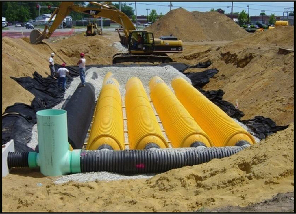
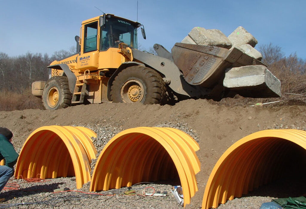
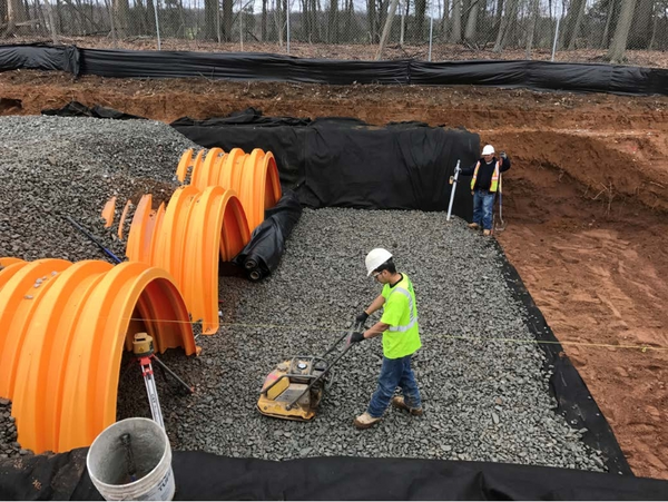
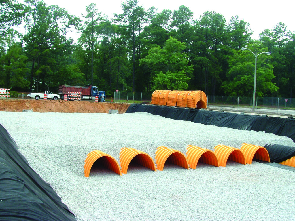
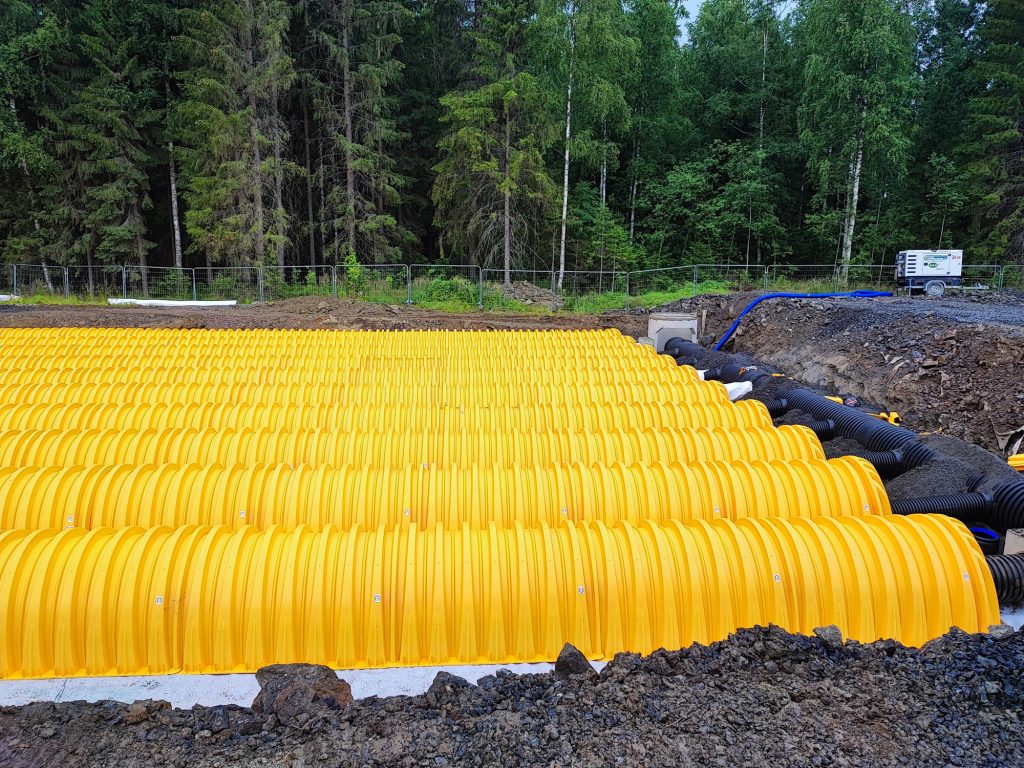
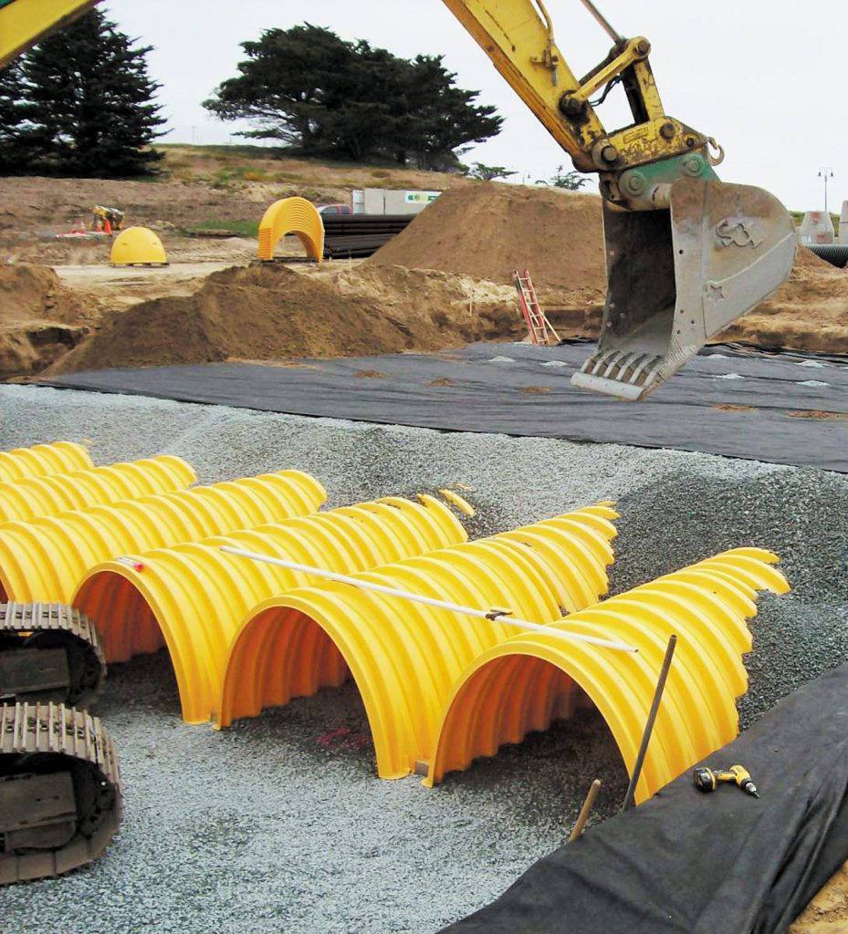
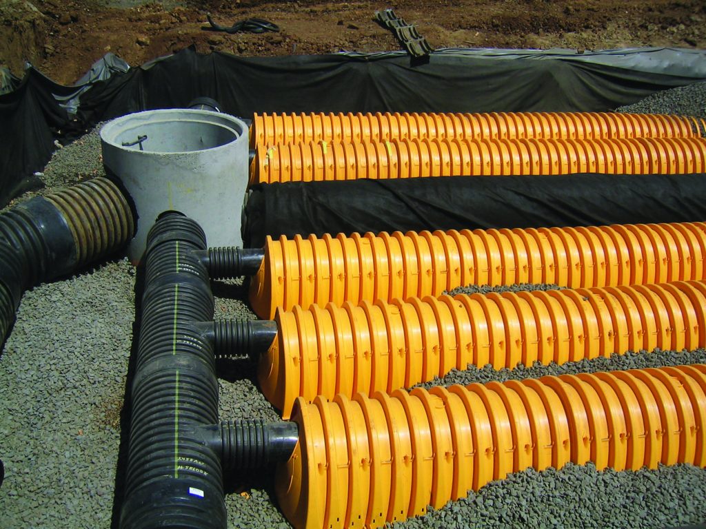
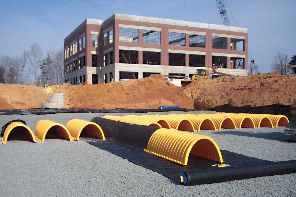
For buried arch-shaped structures, the distribution of loading is different again. The arch shape concentrates the overburden loads through the embedment stone to the spaces between the feet of the arches. The loads are then transferred through a layer of foundation stone to the native subgrade beneath.
Manufacturers should provide technical guidance related to the loading and interactions of their products with the native soil. For instance, ADS’s technical note TN6.22 StormTech Subgrade Performance Considerations does this for arch-shaped chambers.
One of the risks with buried drainage structures is that design responsibilities between the client, designer and manufacturer are often unclear which can mean that the contractor is left to select a product without sufficient information. This risk can be mitigated by a more rigorous approach in the early stages of design.
Recycled aggregate and below-ground SuDS
Recycled aggregate could be used more frequently for installation of below-ground attenuation assets, says Stuart Crisp, UK manager of Advanced Drainage Systems(ADS).
Substituting recycled aggregate for virgin aggregate helps retain natural resources for future generations and can come with cost benefits. Although there is an opportunity to do this with below-ground attenuation assets in sustainable drainage systems (SuDS), contractors often choose to go with what they know–which is the ‘safe’ route of virgin aggregates.
In specifying recycled aggregates, designers and contractors should be aware of the relevant standards, together with any technical guidance from the manufacturer of the attenuation product. BS EN 13242 (+A1:2013) sets out the properties required for aggregates produced from natural, manufactured or recycled materials for hydraulically bound and unbound materials for civil engineering works. Reputable suppliers will provide recycled aggregate with a CE mark to demonstrate conformity to the standard.
Different product manufacturers may have additional requirements for recycled aggregate which is to be used in below-ground SuDS attenuation systems to ensure that it performs its intended functions. For instance, ADS Pipe’s technical guidance for recycled aggregate for its StormTech system calls for a 20/40mm aggregate which is clean, crushed and angular, with less than 5% fines. The reason for limiting fines is that the void space between the aggregate needs to be preserved to allow for the storage and movement of the water through the matrix of aggregate.
Specifications should set out an average porosity for the aggregate. Porosity is the volume of voids over the total volume; this is sometimes confused with void ratio which is the volume of voids over the volume of solids which can lead to installed systems not meeting design requirements.
Other factors to consider when selecting recycled aggregate include the nature of the ground and the ground water and whether there are any potentially aggressive substances present. Sulphites carried in ground water, for example, could react with recycled concrete aggregate and degrade it over time.
Different types of below-ground attenuation systems require different proportions of aggregate to manufactured product. Crates deploy small amounts of aggregate around their perimeter, large-diameter pipes and arch-shaped attenuation products use a greater proportion of aggregate.
With arch-shaped attenuation products, the aggregate around the arches has a dual purpose. It provides structural support, with the elliptical shape of the arches forming the aggregate around them into stone arches and structural columns, transferring the loads away from the chambers into the stiffer material surrounding them. The aggregate also provides additional storage volume which contributes to the efficiency of the attenuation system in terms of its water storage capability.
Recycled aggregate will not necessarily have lower embodied carbon than virgin aggregate, which tends to be supplied from quarries close to the point of installation.
Recycled aggregate can come at a lower cost than its virgin counterpart, again depending largely on transportation distances.
Generally speaking, attenuation products requiring a higher aggregate-to-product ratio tend to have a lower overall carbon footprint per cubic metre of storage than those requiring less aggregate-to-product.
Underground SuDS: derisking the future with standards, certifications andapprovals
Anyone involved in the design, installation or adoption of below-ground SuDS attenuation assets should be doing their due diligence to ensure they are fit for purpose, says Stuart Crisp of ADS.
Below ground attenuation devices for sustainable drainage systems (SuDS), such as crates, are often considered a commodity. The tendency can be to fit the lowest cost option, given the volume of water required by the engineer’s design.
This may function very well on day one. But how can the ultimate asset owner be sure it will function as intended 10, 20 or more years down the line?
This is the question that any SuDS adopting body will be asking, when Schedule 3 of the Flood and Water Management Act 2010 comes into force in England, making SuDS for new developments mandatory. SABs must assess what maintenance and repair costs might be, in order to agree the commuted sum that a developer pays when handing over the asset.
An important part of the due diligence required for below ground SuDS attenuation devices is to check that the products selected meet all the necessary standards, certifications and approvals. To do that properly, it is important to deep dive into the detail of how manufacturers claim that their products comply.
Standards and certifications.
The starting point for any construction product to be used in the UK is that it must, bylaw, have a CE mark or a UKCA mark–although the date from which the UKCA mark will be required has recently been pushed back from June 2025 for at least two years. Next, products must conform to the relevant standards in terms of both functional performance-which is governed mainly by the evaluation, management and testing of the product’s material properties, manufacturing processes and dimensional tolerances–and the structural design process. These two distinct requirements can sometimes be found in two different standards or alternatively in separate parts of the same standard, depending on the product type and material.
British Standards (BS) are the most well known in the UK but in some cases, a harmonised standard, accepted by multiple nations, could apply, which would be designated BS EN or BS ISO in the UK. Note that there cannot be more than one standard covering the same scope in any territory.
For innovative solutions, where a product standard does not exist, manufacturers must take a different approach.
Some choose to cherry pick clauses from different standards in an attempt to demonstrate fitness for purpose, but this is not a reliable approach.
The responsible route is to put the product through an evaluation conducted by a recognised certification body such as the British Board of Agrément (BBA), Water Research Centre (WRc) or British Standards Institution (BSI). This process effectively assesses the key elements that a standard would cover, and checks that the product meets the claims of the manufacturer.
Given the rigour of the testing and checking involved, such approvals understandably take some time to process. ADS was delighted to formally receive its BBA certification for its StormTech range of arch-shaped below ground SuDS attenuation devices in November this year.
Approvals
Across the UK, there are a range of different asset owners that approve SuDS. In England, water companies require developers to follow OFWAT’s Design and Construction Guidance (DCG) for sewers. In addition, the Lead Local Flood Authority (LLFA) must also evaluate and approve drainage designs.
In Scotland, Scottish Water is the adopting body, and SuDS must meet the requirements of Sewers for Scotland 4th edition. The Scottish Environment Protection Agency (SEPA) must also be satisfied that the treatment train is adequate to protect water quality.
In Wales, Schedule 3 of the Flood and Water Management Act was adopted in 2019. The requirement of SABs is based on the Welsh Government’s Statutory Standards for Sustainable Drainage Systems (SuDS) and the CIRIA SuDS Manual, C753.
In a small number of cases, independent adoption bodies such as Icosa Water and Independent Water Networks (IWNL) may take on responsibility for SuDS maintenance. Their requirements are likely to be a version of the DCG.
For devices installed to serve a highway, there is a separate need to demonstrate compliance. For the strategic road network, National Highways’ Design Manual for Roads and Bridges (DMRB) is the most significant document, with local highways authorities often following suit. Products not recognised within National Highways’standards can be used through the Departure from Standards process.
Of course, the compliance requirements touched on in this article are just one part of the due diligence process for SuDS. Below ground attenuation devices can be rendered unfit for purpose due to other parts of the SuDS system such as inadequate treatment capability, or poor maintenance regimes. Systems such as StormTech,where water treatment comes as an integral part of the device, can provide a straightforward way to alleviate that risk.
SuDS design and water quantity: back to basics. Part I. – November 2024
In this, the first of a two-part series considering the fundamentals of SuDS, Stuart Crisp, UK Manager, Advanced Drainage Systems asks if nature-based solutions are an automatic choice when specifying SuDS designed to mimic nature.
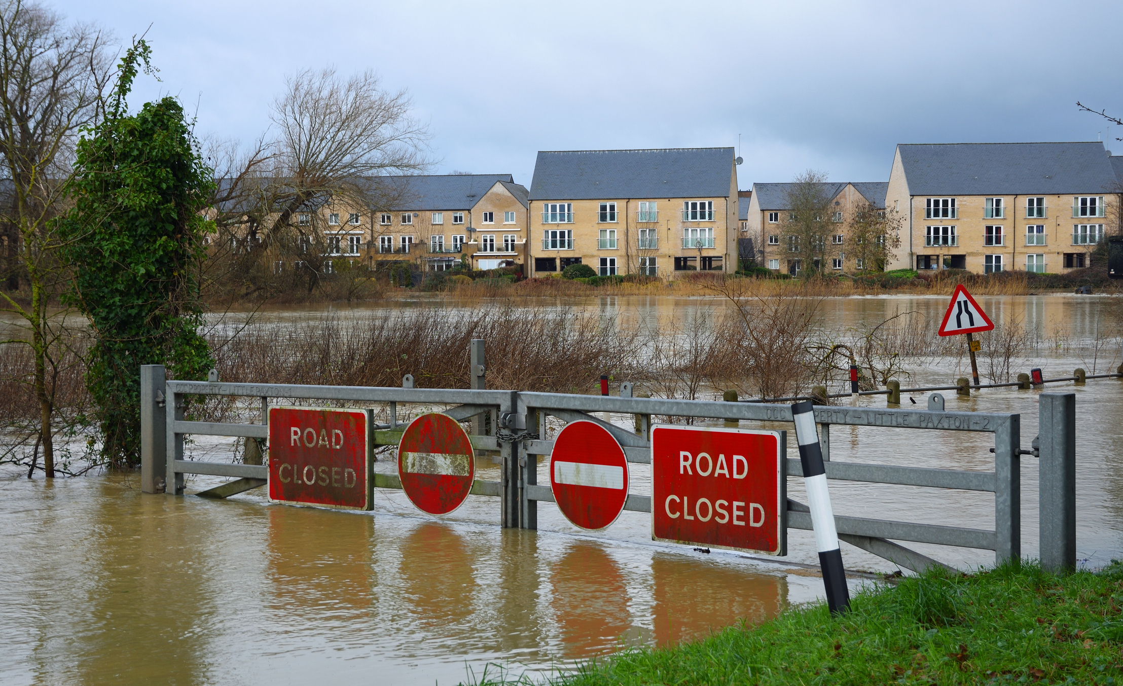
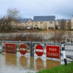
The weather so far this year has provided a stark reminder of the challenges we face due to heavy and intense rainfall. January’s Storm Henk brought a month’s rainfall in four days to some areas, leading to flooding, the worst of it in the Midlands. And in April, the impacts of Storm Kathleen and Pierrick caused flooding across the country,especially on parts of the south coast.
Ten English counties experienced their wettest September on record and for Bedfordshire and Oxfordshire, September 2024 was the wettest calendar month the counties have experienced, in a series dating back to 1836.
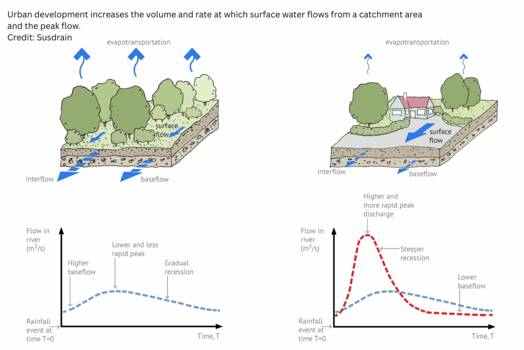
Much of this flooding is exacerbated by urban development. By replacing green fields and vegetation with hard surfaces–roads, roofs and driveways–we change the way and rate at which surface water flows out of an area or catchment.
A good SuDS design for water quantity aims to mimic the flows of water from developed sites so that they are as close as possible to what would have happened,had there still been a greenfield site there. That means throttling the flow of water–in other words providing storage and releasing it later, more slowly–so that it is not rushing so quickly into sewers and water courses and overwhelming them, leading to flooding.
Many policy documents from organisations that currently adopt SuDS–typically Scottish Water in Scotland, the county or unitary authority in Wales or a water company in England mandate natural or green SuDS, often prohibiting the use of proprietary or grey SuDS.
While green SuDS, such as swales and ponds are the right solution for some developments, a blinkered approach may not offer the optimum solution; capital costs could ramp up, it may fail to provide the lowest environmental impact and potentially lead to longer-term problems and higher maintenance and operation costs.
Although designing for water quantity and the urgent need to reduce the risk of flooding is vital, there are the other pillars of SuDS to think about too: water quality, amenity and biodiversity. Previous articles in Drain Trader’s June 2023 and February 2024 issues, looked at water quality issues and what type of management trains were best suited to different types of development, depending on pollutant loads.
Operational and maintenance costs for SuDS schemes are often overlooked and ignored, but the promised implementation of Schedule 3 of the Flood and Water Management Act 2010 in England will shed a harsh light on these. SuDS Approval Bodies (SABs), likely to sit within local authorities, will require robust information about inspection and maintenance regimes and expected costs over the lifetime of a development.
An article in Drain Trader’s March 2023 edition looked at why poorly thought-out SuDS can lead to shorter service lives and higher operational costs than those expected from the design.
Mimicking nature
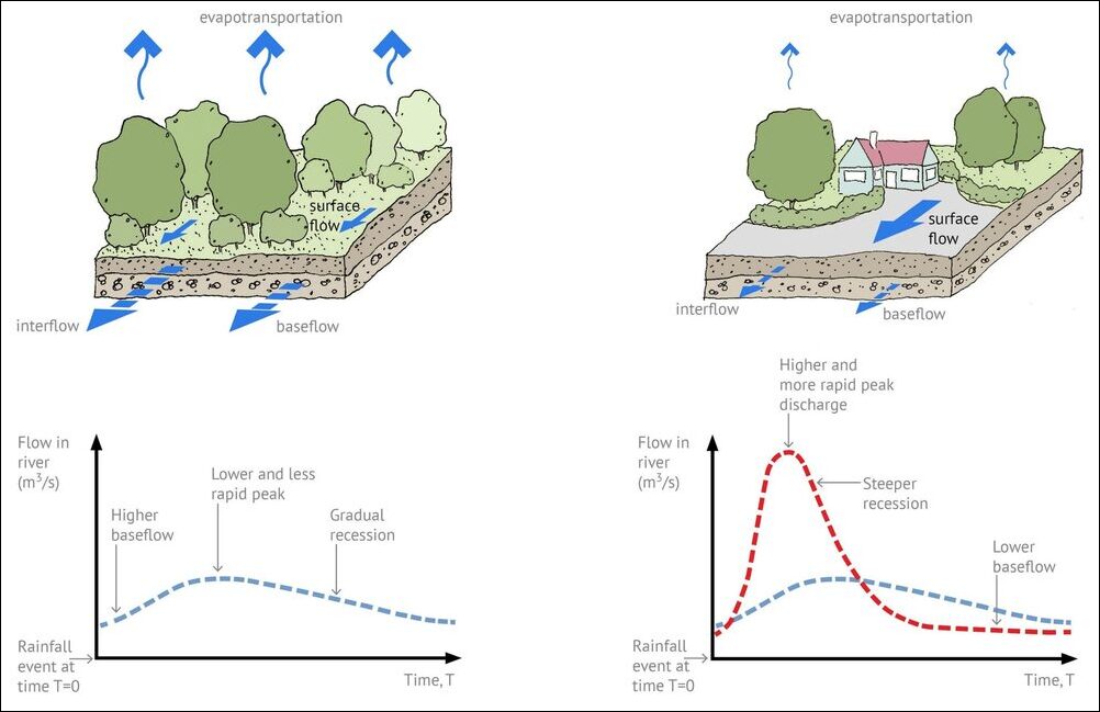
On a greenfield site, the first 5mm of rain would not typically generate surface runoff, it would infiltrate into the ground, evaporate or transpire through the leaves of plants.Then, when water flows from the surface of a catchment and exceeds the capacity of the receiving water body, the additional volume of water would spill over onto the floodplain.
When we develop on that catchment to add impermeable surfaces, such as roofs, roads and hard standings, the amount of surface water runoff generated can increase dramatically. In a dense, urban environment, 95% of the rainfall could flow off the catchment as surface runoff, increasing the volume of water that reaches watercourses or sewers. It is also likely that the peak flow will be higher and come sooner,than had it remained a greenfield site.
CIRIA C753 The SuDS Manual gives a graphical illustration of this. Figure 3.1, in Chapter 3 which deals with design for water quantity, shows hydrographs for the discharge rates of surface water for an area in three situations: when it is greenfield; when developed without flow attenuation; and when developed with flow attenuation.(Figure 1 shows a similar graph, courtesy of SUSDRAIN).
The amount of water that a SuDS system will need to attenuate or store, and the rate at which the water should be discharged is the subject of the hydraulic design for that system. For those that want to go back to first principles, these are set out in BS EN16933-2 Drain and sewer systems outside buildings–Design–Part 2: Hydraulic design.
Today, however, many drainage engineers rely on software such as Info Drainage and Micro Drainage (AutoDesk/Innovyze), Flow (Causeway) and Site3D. But this ‘blackbox’ approach to calculations can mean that designers don’t have the opportunity to properly understand the assumptions and coefficients that have been used–and the impact on water quality based on the SuDS components selected to satisfy the hydraulic design–which may lead to suboptimal performance.
In a SUSDRAIN factsheet from March 2014, Assessing attenuation storage volumes for SuDS–another useful resource for designers–author Anthony McCloy explains the risks of this approach:
“Don’t expect exact answers from the calculation process, it is a usable approximation that can provide acceptable solutions for design. Most of the inputs are based on statistics and calibration factors; therefore we can only ever achieve an approximation of how the system will behave in reality. The results of calculations and modelling need to be used alongside professional judgement to provide the design.”
Ten years later, this point is just as relevant as ever, perhaps even more so as design software is more widely used, with newer generations of engineers never called on to design from first principles. McCloy also advises that those assessing potential SuDS,such as SABs, must also have a basic understanding of first principles of storage volumes and hydraulic design so that they can carry out their statutory duties.
Water storage toolbox
There are many ways that we can create storage for excess surface water. Storage can be online, meaning that flow enters the element, passes through and out the other side or offline where flow enters and exits via the same point. A design could include both online and offline storage where, for example, flow above the 1-in-30-year return period is directed offline to accommodate the 1-in-100-year event.
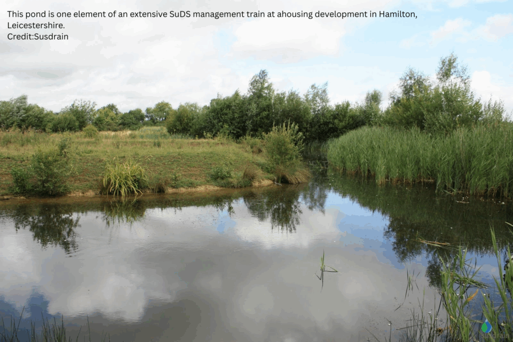
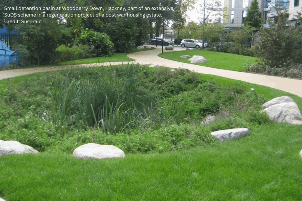
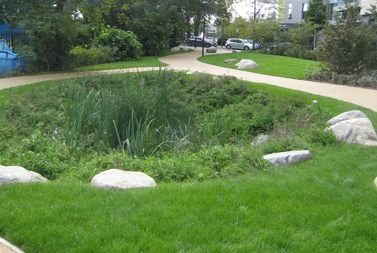
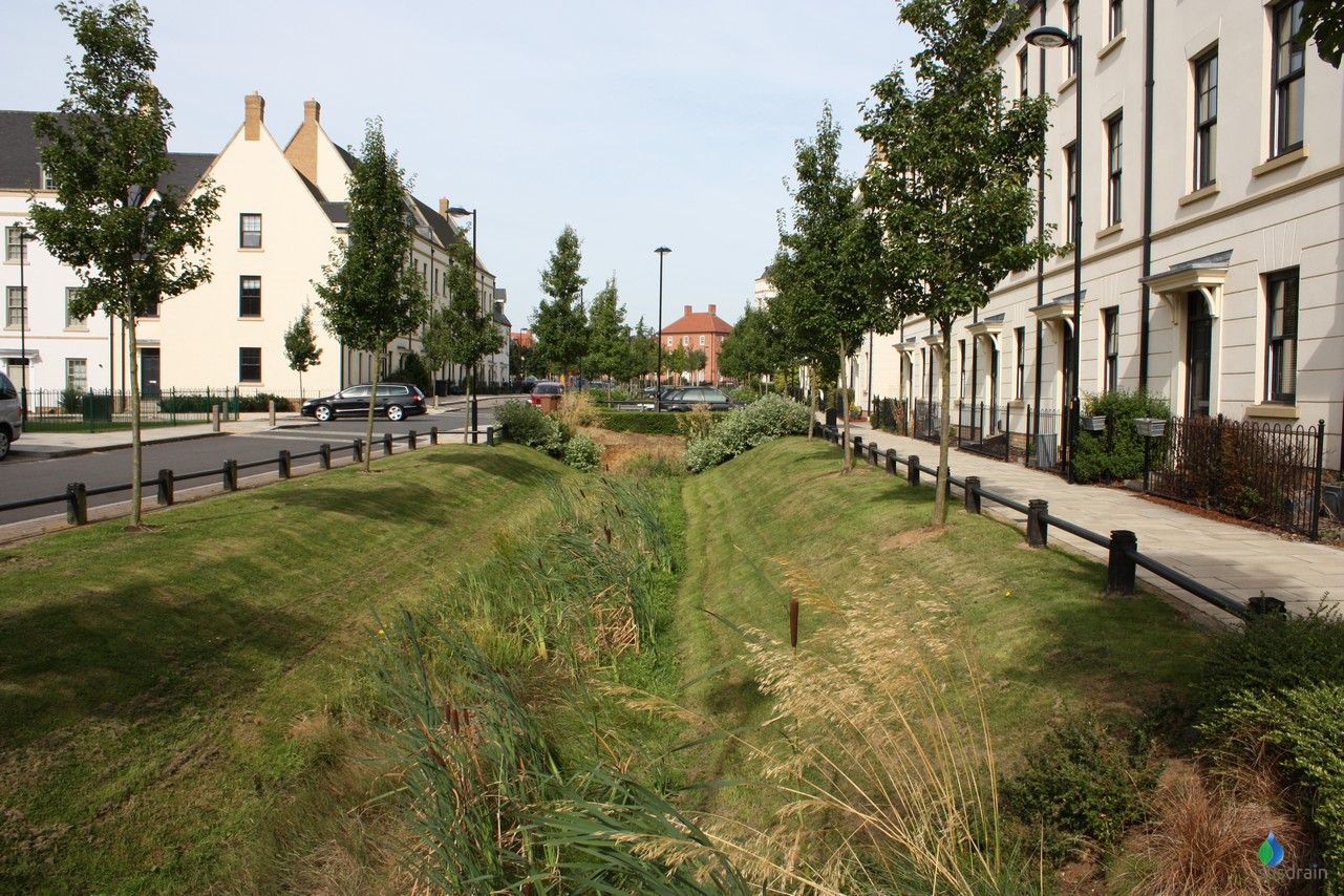
Vegetative or surface-based solutions include ponds, detention basins which are dry until excess water needs to be accommodated and swales which can be used to accommodate volume, as well as to communicate flow between SuDS elements and for infiltration.
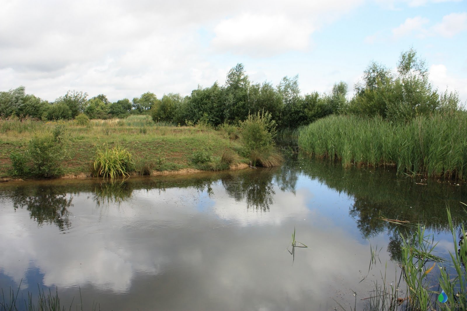
Ponds can be an attractive choice, potentially ticking boxes for all the four pillars of SuDS. From a water quantity perspective, they must have sufficient capacity to cope with rising water levels during higher rainfall events throughout their design lives. Any sediment entering the pond will settle out quickly, since the sediment particles soon reach terminal velocity allowing them to settle to the bottom of the pond.
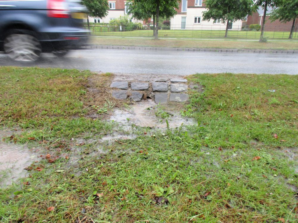
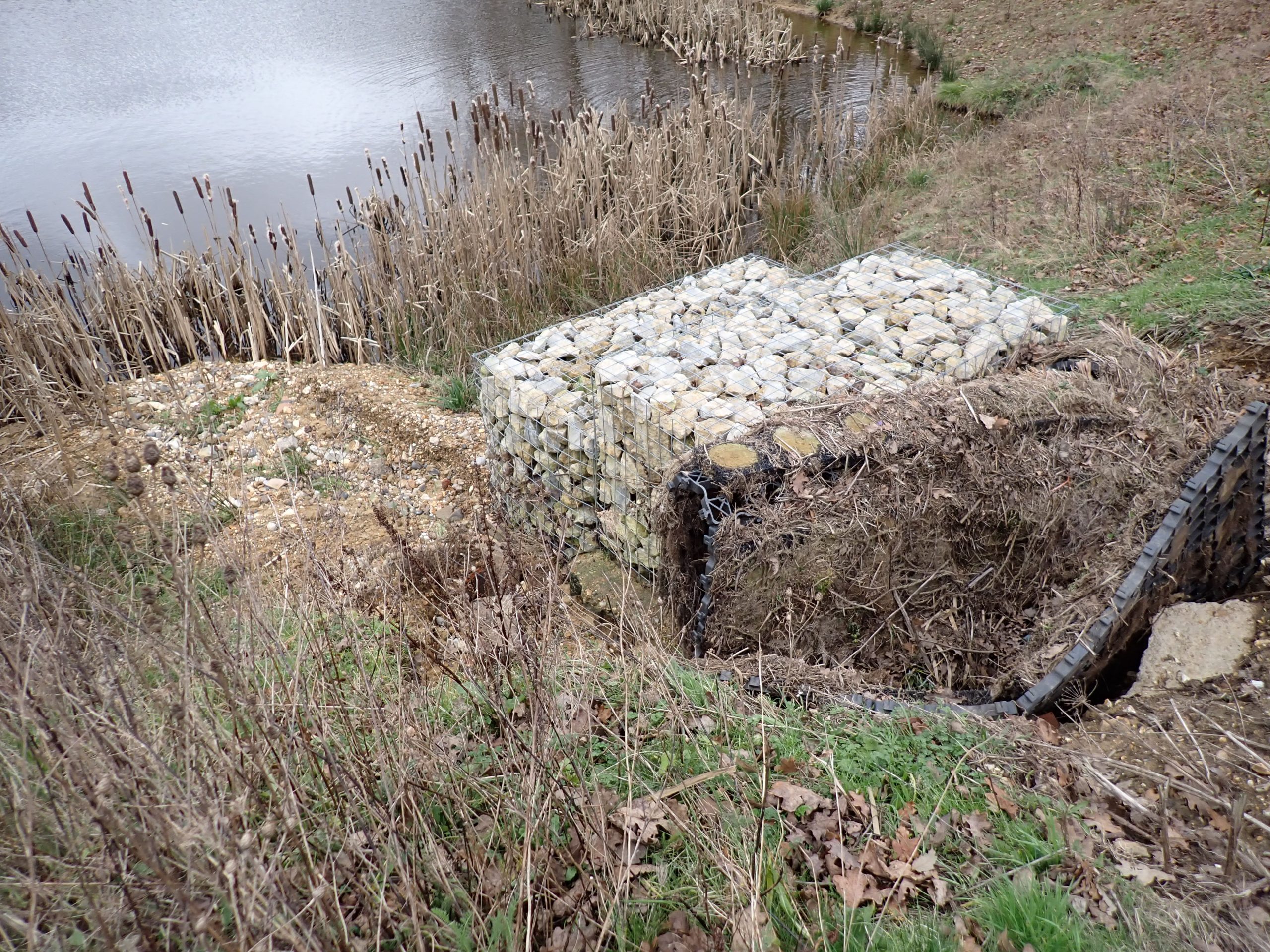
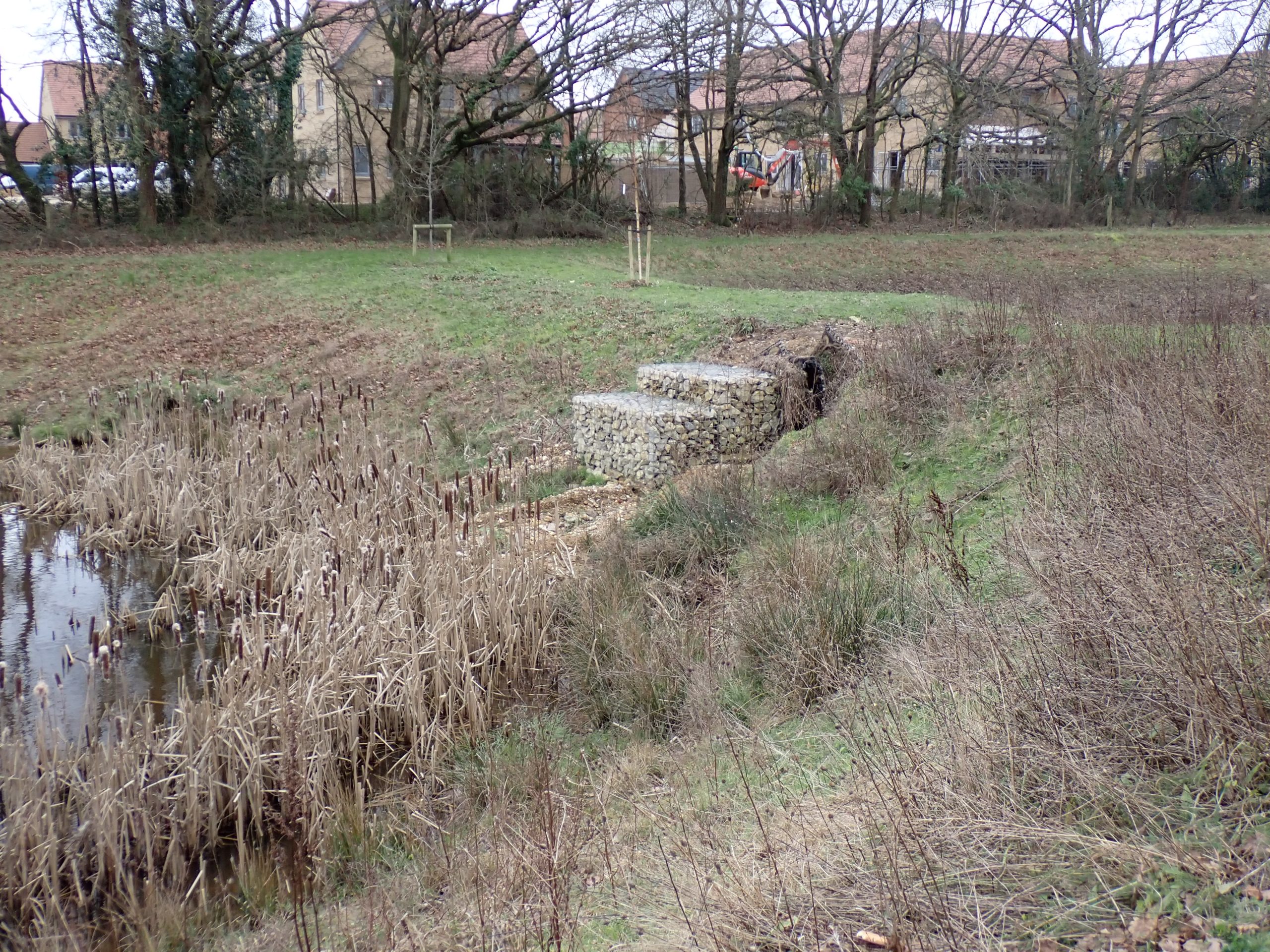
As an asset owner or adopter, it is important to anticipate the amount of sediment that will settle out over time, because the accumulated sediment must be somehow removed at intervals to allow the pond to provide sufficient storage volume. One issue that is sometimes overlooked in the design of ponds is providing safe and cost-effective means of accessing the pond to remove sediment when required.
A recent story from Gloucestershire illustrates the costs involved. Local residents petitioned Gloucester City Council in January this year to desilt Saintbridge pond in Abbeydale because it produces a foul smell in the summer and the silt is negatively impacting on water quality and habitats. The council refused, saying that it was only 15 years since it last desilted the pond and that the operation would cost £700,000.
Commenting on the story, Jo Bradley, director of operations at Stormwater Shepherds,pointed out the error of not having installed an upstream sediment separator at the same time as the pond. “If a manufactured sediment separator had been included, it could have been emptied every year, costing maybe £700-£1000. That would have cost up to £20,000 over the 20-year cycle and avoided the £700,000 cost that they are now facing.
”Bradley pointed out that by bringing in heavy plant every 20 years, removing vegetation and sediment, the pond’s habitats and inhabitants are disturbed, negatively impacting on nature. And she added that the sediment in the pond could well be contaminated with toxic, bio-accumulative pollutants and tyre-wear particles. CIRIA’s manual says that a sediment separator or sediment forebay should be installed upstream of every pond. And, depending on the pollutants likely to be washed into the pond with the surface water, other pre-treatment could be needed. Without this, there is a danger that wildlife will be attracted to the pond, only to suffer harm from the pollutants within it.
This point was illustrated by researchers at Glasgow University, who compared SuDS ponds with natural ponds and found that pollutants were higher in some of the SuDS ones, negatively affecting amphibian breeding and development. A paper published on the research issues this warning:
“The function of SuDS and other urban drainage systems to sequester pollutants increases their potential to be ecological traps by advertising false cues of suitable habitat.
”In the next issue, Stuart considers what the options are available when considering proprietary attenuation solutions.
ADS extends StormTech SuDS attenuation and storm water treatment range
The new StormTech SC-800 arch-shaped chamber from Advanced Drainage Systems (ADS), a global leader in corrugated thermoplastic drainage pipes and a specialist in water management systems; not only holds more water than the company’s current best-selling and most popular chamber – the SC-740 – but also requires less embedment stone for installation, and has a reduced minimum cover depth, resulting in greater storage capacity for the same footprint area and depth, plus reduced construction time and cost.
The SC-800 maximizes storage within a compact footprint while its corrugated design pares down the minimum cover depth and provides superior structural integrity. The latest development in the company’s drive to reduce footprints sees the SC-800 with a 7% smaller footprint than the SC-740 for the same storage volume.
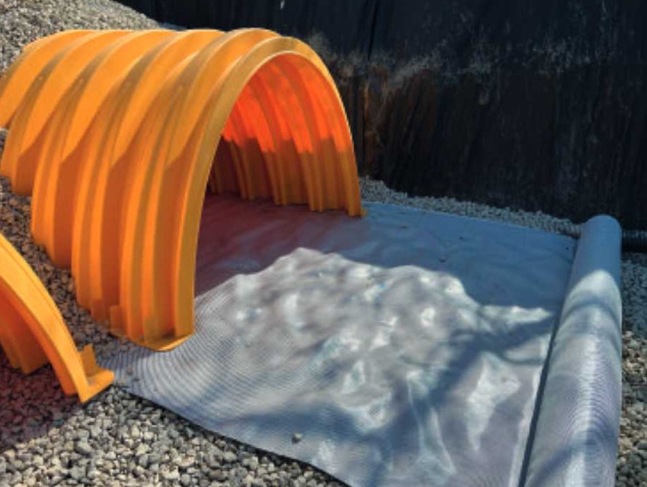
Unlike other below-ground SuDS attenuation systems such as crates and pipes, which allows runoff into the entire tank storage space, the StormTech arch-shaped system directs first flush flow into the patented Isolator Row – an integral water quality treatment device that has two treatment stages: sedimentation and filtration.
Isolator Row is independently tested and validated to remove more than 80% Total Suspended Solids (TSS), often avoiding the need for a costly sediment removal system upstream of the tank. Isolator Row can also remove other pollutants such as particulate-bound hydrocarbons and metals.
Another two treatment stages can take place within the embedment stone: adsorption and biodegradation, leading to even greater removal efficiencies. Isolator Row is the only part of a StormTech system that needs maintenance, as the other chambers only receive ‘clean’ untreated runoff from flows exceeding the first flush flow rate.
Cleaning is carried out at intervals of typically two to five years, depending on local conditions, using standard sewer jetting equipment and a vacuum tanker to remove the waste.
StormTech’s arch design sheds load from the chamber to the surrounding stone, which forms a structural arch that transfers loads into stone columns between the chambers and spreads the load through to the native soil, resulting in extraordinary minimum and maximum cover depths. The new SC-800 chamber has a minimum cover depth of 375mm. All StormTech standard installation details are based on HGV traffic loading.
The design of StormTech chambers means that the units can be stacked, taking up a minimum of space for transportation, storage and to speed-up installation.
By adding SC-800 into the StormTech range, ADS has enhanced design flexibility for SuDS attenuation and storm water management. This innovation exemplifies ADS’s commitment to providing cutting-edge products that meet the evolving needs of the construction industry.
For more information on Advanced Drainage Systems, visit www.adspipe.co.uk.
SuDS design & water quantity: back to basics
SuDS design and water quantity: back to basics
The purpose of SuDS – sustainable drainage systems – is to mimic nature. But should that automatically mean that we only consider nature-based solutions, asks Stuart Crisp.
The weather so far this year has provided a stark reminder of the challenges we face due to heavy and intense rainfall. In January, Storm Henk brought a month’s rainfall in four days to some areas, leading to flooding, the worst of it in the Midlands. And in April, the impacts of Storm Kathleen and Pierrick caused flooding across the country, especially on parts of the south coast.
Much of this flooding is exacerbated by urban development. By replacing green fields and vegetation with hard surfaces – roads, roofs and driveways – we change the way and rate at which surface water flows out of an area or catchment.
A good SuDS design for water quantity aims to mimic the flows of water from developed site so that they are as close as possible to what would have happened, had there still been a greenfield site there. That means throttling the flow of water – in other words providing storage and releasing it later, more slowly – so that it is not rushing so quickly into sewers and water courses and overwhelming them, leading to flooding.
Many policy documents from organisations that currently adopt SuDS – typically Scottish Water in Scotland, the county or unitary authority in Wales or a water company in England mandate natural or green SuDS, often prohibiting the use of proprietary or grey SuDS.
While green SuDS, such as swales and ponds are the right solution for some developments, a blinkered approach may not best mimic nature, could ramp up capital costs and potentially lead to longer-term problems and higher maintenance and operation costs.
Although designing for water quantity and the urgent need to reduce the risk of flooding is vital, there are the other pillars of SuDS to think about too: water quality, amenity and biodiversity. Previous articles in Drain Trader’s June 2023 and February 2024 issues, looked at water quality issues and what type of management trains were best suited to different types of development, depending on pollutant loads.
Operational and maintenance costs for SuDS schemes are often overlooked and ignored, but the promised implementation of Schedule 3 of the Flood and Water Management Act 2010 in England will shed a harsh light on these. SuDS Approval Bodies (SABs), likely to sit within local authorities, will require robust information about inspection and maintenance regimes and expected costs over the lifetime of a development.
An article in Drain Trader’s March 2023 edition looked at why poorly thought-out SuDS can lead to shorter service lives and higher operational costs than those expected from the design.
Mimicking nature
On a greenfield site, the first 5mm of rain would not typically generate surface runoff, it would infiltrate into the ground, evaporate or transpire through the leaves of plants. Then, when water flows from the surface of a catchment and exceeds the capacity of the receiving water body, the additional volume of water would spill over onto the floodplain.
When we develop on that catchment to add impermeable surfaces, such as roofs, roads and hardstandings, the amount of surface water runoff generated can increase dramatically. In a dense, urban environment, 95% of the rainfall could flow off the catchment as surface runoff, increasing the volume of water that reaches water courses or sewers. It is also likely that the peak flow will be higher and come sooner, than had it remained a greenfield site.
CIRIA C753 The Suds Manual gives a graphical illustration of this. Figure 3.1, in Chapter 3 which deals with design for water quantity, shows hydrographs for the discharge rates of surface water for an area in three situations: when it is greenfield; when developed without flow attenuation; and when developed with flow attenuation. (Figure 1 shows a similar graph, courtesy of SUSDRAIN).
The amount of water that a SuDS system will need to attenuate or store, and the rate at which the water should be discharged is the subject of the hydraulic design for that system. For those that want to go back to first principles, these are set out in BS EN 16933-2 Drain and sewer systems outside buildings – Design – Part 2: Hydraulic design.
Today, however, many drainage engineers rely on software such as InfoDrainage and MicroDrainage (AutoDesk/Innovyze), Flow (Causeway) and Site3D. But this ‘black box’ approach to calculations can mean that designers don’t have the opportunity to properly understand the assumptions and coefficients that have been used – and the impact on water quality based on the SuDS components selected to satisfy the hydraulic design – which may lead to a suboptimal design.
In a SUSDRAIN factsheet from March 2014, Assessing attenuation storage volumes for SuDS – another useful resource for designers – author Anthony McCloy explains the risks of this approach:
“Don’t expect exact answers from the calculation process, it is a usable approximation that can provide acceptable solutions for design. Most of the inputs are based on statistics and calibration factors; therefore we can only ever achieve an approximation of how the system will behave in reality. The results of calculations and modelling need to be used alongside professional judgement to provide the design.”
Ten years later, this point is just as relevant as ever, perhaps even more so as design software is more widely used, with newer generations of engineers never called on to design from first principles. McCloy also advises that those assessing potential SuDS, such as SABs, must also have a basic understanding of first principles of storage volumes and hydraulic design so that they can carry out their statutory duties.
Water storage toolbox
There are many ways that we can create storage for excess surface water. Storage can be online, meaning that flow enters the element, passes through and out the other side or offline where flow enters and exits via the same point. A design could include both online and offline storage where, for example, flow above the 1-in-30-year return period is directed offline to accommodate the 1-in-100-year event.
Vegetative or surface-based solutions include ponds, detention basins which are dry until excess water needs to be accommodated and swales which can be used to accommodate volume, as well as to communicate flow between SuDS elements and for infiltration.
Ponds can be an attractive choice, potentially ticking boxes for all the four pillars of SuDS. From a water quantity perspective, they must have sufficient capacity to cope with rising water levels during higher rainfall events throughout their design lives. Any sediment entering the pond will settle out quickly, since the sediment particles soon reach terminal velocity allowing them to settle to the bottom of the pond.
As an asset owner or adopter, it is important to anticipate the amount of sediment that will settle out over time, because the accumulated sediment must be somehow removed at intervals to allow the pond to provide sufficient storage volume. One issue that is sometimes overlooked in the design of ponds is providing safe and cost-effective means of accessing the pond to remove sediment when required.
A recent story from Gloucestershire illustrates the costs involved. Local residents petitioned Gloucester City Council in January this year to desilt Saintbridge pond in Abbeydale because it produces a foul smell in the summer and the silt is negatively impacting on water quality and habitats. The council refused, saying that it was only 15 years since it last desilted the pond and that the operation would cost £700,000.
Commenting on the story, Jo Bradley, director of operations at Stormwater Shepherds, pointed out the error of not having installed an upstream sediment separator at the same time as the pond. “If a manufactured sediment separator had been included, it could have been emptied every year, costing maybe £700 – £1000. That would have cost up to £20,000 over the 20-year cycle and avoided the £700,000 cost that they are now facing.”
Bradley pointed out that by bringing in heavy plant every 20 years, removing vegetation and sediment, the pond’s habitats and inhabitants are disturbed, negatively impacting on nature. And she added that the sediment in the pond could well be contaminated with toxic, bio-accumulative pollutants and tyre-wear particles.
CIRIA’s manual says that a sediment separator or sediment forebay should be installed upstream of every pond. And, depending on the pollutants likely to be washed into the pond with the surface water, other pre-treatment could be needed. Without this, there is a danger that wildlife will be attracted to the pond, only to suffer damage.
This point was illustrated by researchers at Glasgow University, who compared SuDS ponds with natural ponds and found that pollutants were higher in some of the SuDS ones, negatively affecting amphibian breeding and development. A paper published on the research issues this warning: “The function of SuDS and other urban drainage systems to sequester pollutants increases their potential to be ecological traps by advertising false cues of suitable habitat.”
Proprietary attenuation
The most commonly used proprietary solutions include permeable paving, where the water passes through the gaps between blocks to be stored in unbound granular material below them; geocellular crates which are buried below ground; and large-diameter pipes below ground. There are also innovative systems, new to the UK, such as arch-shaped chambers which combine both filtration and attenuation without the need for additional upstream devices.
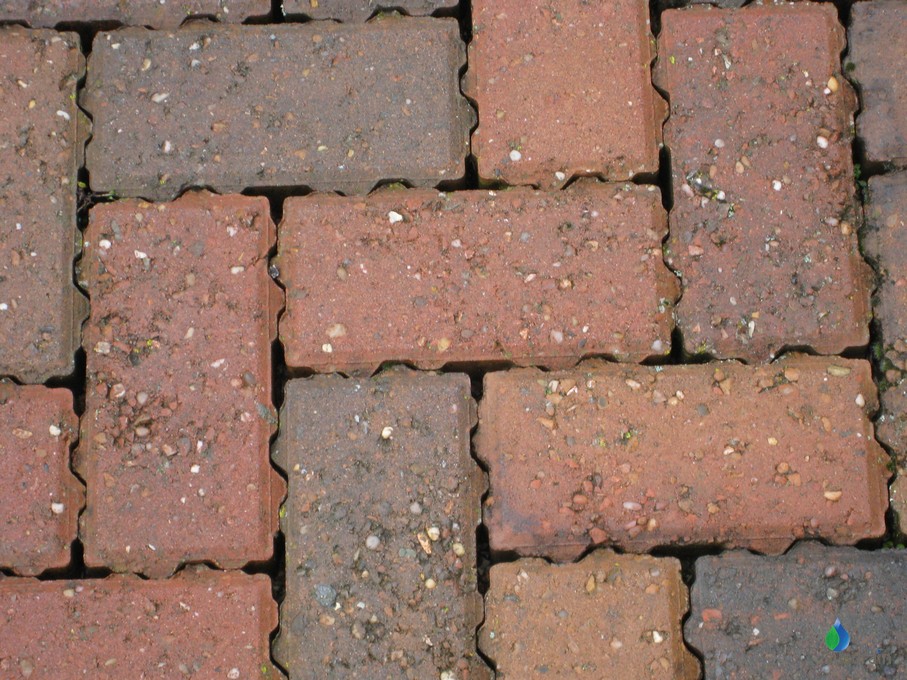
Permeable block paving can be useful because it requires a limited volume of excavation. In terms of water quality, block paving provides two stages of water treatment: water is filtered as it passes through the gaps between blocks and pollutants can then be broken-down by bacteria naturally present as it passes through the granular fill beneath it and then either infiltrates the ground or flows into another part of the system.
The capacity of permeable paving to accommodate surface runoff decreases over time. And regular maintenance is needed to clean out the joints between the paving blocks so that they do not become clogged up, making sure that the wash water does not enter the drainage system served by the permeable pavement. Also, note that water companies do not adopt permeable paving as it is not only a SuDS component, but also a structural pavement.
Geocellular crates can be a good choice if there is a limited plan area for water storage, since they provide a large volume for a limited footprint. They are typically manufactured from polypropylene (PP) or PVC by injection molding, or extrusion of joining thermoformed sheets.
Crate-based systems are relatively simple to design and due to their lightweight and modular construction, they are easy to install. There are a variety of types on the market, from shallow sub-base replacement systems to be used beneath car parks to crates which can be used at a greater depth for higher volumes of storage.
However, crates are likely to decrease in storage capacity over time. Installation of catchpits, silt separators and other sediment pre-treatment measures upstream are required – but often under-designed, which can lead to issues as maintenance to remove sediment build up in crate-based systems can be difficult or impossible. There are also question marks over their long-term durability, as some crates do not comply with the latest industry specifications for structural integrity.
Clause 21.5.3 and Table 21.2 of the SuDS Manual suggests adding an additional 10% to the storage volume of crates to account for sediment build up. Asset owners and adopters of SuDS systems should determine if a crate-based system has been appropriately up-sized by 10% and if not, that the SuDS designer or manufacturer has provided evidence to demonstrate that all the sediment can be removed from the crate-based system. Not all adopting bodies will accept crates.
Large diameter pipes, laid as a single run or in parallel, with manifolds are an established solution, one of the forerunners of proprietary underground water attenuation which can be created from existing products. They can be a cost-effective choice with concrete and plastic the most commonly used materials; thin steel pipes and a hybrid plastic and steel product are other choices.
A downside to large-diameter pipes is that they are larger and can be heavier to transport and install, requiring more transport movements for delivery, more storage space on site and a larger excavation footprint. Depending on the type of pipe material, they may not be adoptable by some asset owners.
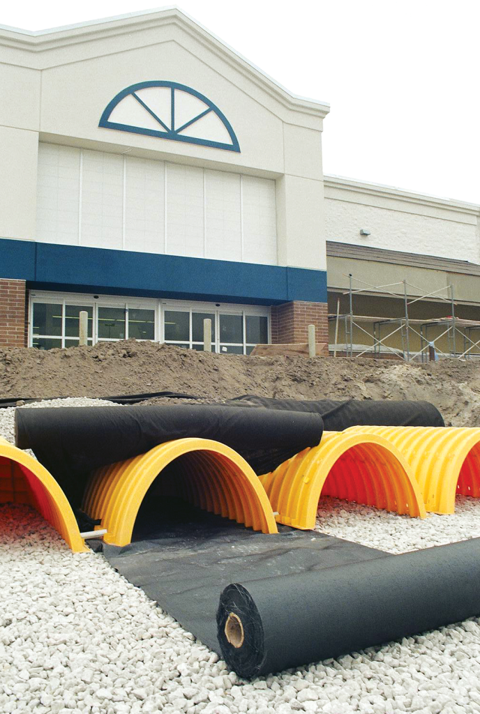
Innovative underground water storage systems such as arch-shaped chambers are simple to design and install and can be configured to fit irregular areas or to fit around existing infrastructure or obstacles. Their arch shape means that the embedment material around them is shaped into ‘stone columns’ allowing them to be installed at shallower depths, while taking heavier loadings. They are lightweight and stackable which means they are easy to transport, store and install.
One proprietary brand of arches, StormTech, can be installed with an integrated pre-treatment element, Isolator Row, which takes out sediments and other surface water pollutants from the first flush of a rainfall event. The inclusion of Isolator Row can remove the need to install upstream pre-treatment devices such as sediment traps and bypass separators, resulting in considerable cost savings. StormTech has been designed for ease of maintenance, since only Isolator Row needs to be cleaned, accessed from the manhole using standard sewer cleaning equipment.
This brand of arches provides four stages of water treatment: Isolator Row provides the first two stages. Sedimentation – gravity separation of the silt particles, settling out on the bed of Isolator Row – and filtration, as the water passes through a layer of woven geotextile fabric.
The next two treatment stages are akin to that for permeable concrete block paving; that is adsorption as the water passes over the granular material surrounding the chambers and biodegredation from the action of bacteria breaking down pollutants into non-polluting material. StormTech meets the requirements for adoption by water companies as set out in the Design and Construction Guidance (DCG) for adoptable sewers.

Green and grey
Attenuation of surface water in vegetative SuDS can be a good solution for some developments, particularly where there is lots of space and low pollutant loads. But insisting that they are the only choice could lead to designs which do not best mimic nature or provide the best options.
A more flexible approach to SuDS would allow a combination of green and grey elements to be deployed. This could allow some water to be stored in green SuDS such as ponds and swales, with proprietary solutions such as below-ground pre-treatment devices and attenuation chambers, deployed elsewhere. Alternatively, crates or arched chambers could be installed as additional storage beneath a smaller pond or under a parking area to deliver multiple SuDS benefits within a smaller available footprint.
A good SuDS design also factors in the cost and ease of maintenance of the various SuDS elements. There is a misconception that natural SuDS can be left to nature, but this is not the case. Vegetation needs to be maintained, litter must be picked at frequent intervals and for ponds, sediment build-up needs to be removed, as explained above, to maintain the capacity of the pond.
Equally for proprietary SuDS elements, maintenance to preserve the hydraulic capacity of water storage and the functioning of water quality treatment devices is an important consideration. When products are substituted in ‘value-engineering’ exercises which are, in fact, capital cost reduction exercises, the impact on water quality is often overlooked. Although pollutant loads could look low enough that upstream treatment is not needed, there will be a need to consider the long-term performance of the SuDS system over the lifetime of the development.
Finally, there is the issue of climate change. Although SuDS designs do apply factors to account for increasing rainfall intensity and frequency, they do not consider the fact that more intense periods of rainfall increase the amount of sediment and pollutants that are swept along with surface water. Add an extended dry period before that rainfall event, and the problem will be worse.
To limit designers to vegetative SuDS is to limit the choice of tools they have available to them. With a bigger toolbox of grey and green SuDS elements, they have a greater opportunity to create solutions that are technically, environmentally and economically viable over their entire lifetimes.
For more information on Advanced Drainage Systems, visit www.adspipe.co.uk.
Crate Expectations
With strengthening focus on flooding and water quality, CIRIA’s advice to oversize crate-based attenuation tanks by 10% has never been more relevant, says Stuart Crisp, UK manager at Advanced Drainage Systems (ADS).

There’s a reason why the CIRIA SuDS Manual C753 suggests that “difficult to clean” SuDS attenuation systems, such as below-ground crates, should be oversized by 10%: there is a risk that sediment will build up in them, reducing their storage capacity.
With increasing legislation to manage flood risk and to prevent pollution, and more intense rainfall events, this advice becomes even more pertinent. There is a higher volume of water for SuDS devices to deal with and, when these events follow dry spells, more particulate matter and pollutants are swept along with surface water.
Unfortunately, this need to upsize crate-based attenuation tanks by 10% is often overlooked, thanks to focus on originally calculated target storage volumes. Furthermore, if the development is ‘value-engineered, the capital cost saving also often focusses on the original target storage volume. Up-sizing is often disregarded and, if the design is substituted for another type of attenuation system, the implications for water quality and the effectiveness of the treatment train are ignored.
The result is an increased risk of flooding and an increased risk to water quality.
Risk-based approach
The SuDS manual suggests a risk-based approach to designing SuDS management trains. Considering sediment, this means assessing: how much is likely to build up, depending on the location, how that load might change over time, and how often and easily devices will need to be cleaned.
Clause 21.5.3 of the manual explains the rationale for upsizing below-ground attenuation by 10%, while Table 21.2 shows the potential loss of storage capacity. Typically, commercial developments suffer from the highest sediment loading, followed by car parks, high-density residential developments and highways.
Removing sediment is also necessary to protect water quality and to avoid the negative impacts of pollutants. The predicted type, quantity and concentration of pollutants governs the choice of natural or manufactured SuDS element that would be most suitable.
Some underground attenuation systems, such as ADS’s StormTech arched system with its Isolator Row, are designed with in-built treatment systems which can be easily cleaned using standard equipment. This can negate the need for – and cost of – upstream treatment devices, while still protecting attenuation capacity and water quality.
Pay now or pay later
With the anticipated implementation of Schedule 3 of the Flood and Water Management Act 2010, SuDS adopting bodies will be looking hard at maintenance issues. Asset owners will need to be assured that the SuDS they are taking on will perform as designed throughout their whole lives.
Short-term savings in capital cost, which skimp on capacity and compromise water quality, can lead to long-term problems and greater whole-life costs, resulting in higher commuted sums for developers and an additional, avoidable cost burden on UK plc.
If a system is claimed to be exempt from the 10% up-sizing guidance, evidence that the system can be completely and easily cleaned should be demanded.
For more information on Advanced Drainage Systems, visit www.adspipe.co.uk.
Future-proofing for Schedule 3
With legislation mandating SuDS and their adoption for new developments on the horizon, developers and designers need to upskill to ensure future designs meet tough new standards.
The Government’s recent announcement that it intends to implement Schedule 3 of the Flood and Water Management Act 2010, is a game changer for SuDS. It means that SuDS adoption is expected to be mandatory in England, as it has been in Wales since 2019. In Scotland, Schedule 3 has not been implemented, but SuDS is generally a requirement within planning legislation.
“While developers currently have the right to connect drainage systems into sewers, that is unlikely to be the case anymore,” explains Stuart Crisp, UK manager at Advanced Drainage Systems (ADS). “Instead, they will have to show that they have included SuDS in their schemes and demonstrate how that SuDS system can be maintained over the lifetime of a development.”
Subject to a consultation later this year, implementation of Schedule 3, which includes SuDS approval and adoption, is expected in late 2024. That means that there is less than two years for concerned professionals to get up to speed with the range and implications of possible solutions, both above and below ground.
“Designers will have to think about more than just hydraulic design, to include whole life maintenance and treatment train to deal with water quality issues and specific pollutants,” says Crisp. “There will probably be a transition period as Schedule 3 comes in, but it makes sense to upskill now in order to future-proof designs.”
Currently, SuDS can be adopted by water companies as long as systems comply with the Design and Construction Guidance (DCG) which sets out how SuDS should be delivered. However, it is not compulsory for a developer to jump through the adoption hoops, leading to some assets not being of a prescribed, consistent standard of quality and performance or properly maintained and monitored, leading to problems down the line.
DCG was updated last year to include arch-shaped below-ground attenuation structures, such as ADS’s StormTech. StormTech offers a flexible and cost-efficient alternative to other below-ground attenuation structures such as crates or large-diameter pipes, with the benefit of built-in pollution treatment, reducing the extent of additional treatment elsewhere in the SuDS system.
It is expected that Schedule 3 will change the adopters of SuDS to become SuDS approving bodies (SABs) which will be within unitary councils or county councils. And it will bring in new statutory guidance, taking over from DCG to cover design, construction and operation over an asset’s lifetime.
“The statutory requirements in England are likely to be more onerous than both DCG and the current non-statutory standards in terms of what will be acceptable for planning approval and adoption after construction,” warns Crisp. “SuDS adoption becoming mandatory, with few exceptions, will raise the bar. Happily, poor quality products and poorly executed designs are likely to disappear from the market.”
For anyone looking to start the upskilling process now, manufacturer training and CPDs, such as those on below-ground attenuation offered by ADS, are already available and should include information on legislation, best practice and comparable systems.
For more information on Advanced Drainage Systems, visit www.adspipe.co.uk.
Water Quality and Data: A Matter of Trust
SuDS designs must consider water quality and water quantity in parallel – and use robust design data to avoid problems for asset owners, warns Stuart Crisp, UK manager at Advanced Drainage Systems (ADS).
SuDS design is becoming ever more complex. There’s a growing awareness that we must look after our water quality more carefully, backed up by policy such as the Plan for Water, published last year.
Where there are risks that surface water will carry pollutants, it must be treated, whether using natural or proprietary components, to reduce them to where they are not considered harmful to the environment. Where pollutant loads are low, natural vegetative SuDS may be able to do that job. Where they are higher, some form of manufactured treatment may be needed.
The asset owner needs to be assured that all the components of a SuDS system will perform as designed in relation to water quality as well as water quantity – and that they will continue to do so over the lifetime of the development. That includes ensuring that the data related to the pollutant removal capability of those components is robust. Otherwise, there is a risk that an asset becomes a liability.
Designing for water quality
The CIRIA SuDS Manual C753 suggests a risk-based approach for designing water quality in SuDS management trains – the series of components that make up the drainage system. It provides pollution hazard indices for different types of site, and for three forms of pollution: total suspended solids (TSS), metals and hydrocarbons. It also gives mitigation indices (MIs) for natural SuDS components.
The designer must then select components whose combined MIs meet or exceed the pollution hazard indices for the predicted pollutants, noting that only 50% of the published MI value can be used for components downstream of the first treatment stage.
For manufactured components, British Water’s 2022 how to guide, Applying The CIRIA SuDS Manual (C753) Simple Index Approach To Proprietary Manufactured Stormwater Treatment Devices, provides a method for calculating mitigation indices for TSS, metals and hydrocarbons. This allows manufacturers of treatment devices to publish their MIs to a recognised methodology and designers can select the right combination of elements in a SuDS management train using reliable data, verified by a third party, to meet the pollution hazard indices of a development area.
Adopting a problem
Although it now looks like Schedule 3 of the Flood and Water Management Act 2010 may not be activated until 2025, England will need to meet more demanding requirements for water quality. At this point, the body adopting the SuDS must ensure that they are taking on something that performs as claimed over the whole of its lifetime.
Our advice would be to do due diligence to determine how MIs have been derived, what methodology was applied and to insist that the process and results have been verified by a third party expert.
For more information on Advanced Drainage Systems, visit www.adspipe.co.uk.
Water qualitatively and quantitively: managing storm water down a ‘treatment train’
HISTORICALLY, driven by legislation, there’s a tendency to focus on water quantity – how to use SuDS to reduce or delay release of stormwater into sewers and prevent flooding. However, new legislation requires the additional focus on water quality. The SuDS treatment train considers water quality and prevention of pollution from stormwater runoff (alongside flood risk mitigation), with the level of treatment provided based on the anticipated levels and types of pollution.
A SuDS treatment (or management) train should start with prevention such as reducing impermeable surfaces, to reduce run-off and remove sources of pollution. Next comes source control, where rainfall is dealt with close to where it falls by infiltration-based elements such as soakaways, rain gardens and permeable pavements. Site control sees water managed within a local area, for instance directing water to a soakaway or infiltration device and then onto an attenuation pond or tank. Finally, regional control would see a system that could handle run-off from several sites, perhaps resulting in a detention basin or wetland.
The SuDS Manual, C753, published by CIRIA, prescribes a risk-based approach to designing SuDS for water quality. If pollution risks are deemed to be low, then SuDS designers can prioritise water quantity, amenity and biodiversity. If they are medium, then all considerations must be balanced. And if they are high, water quality evaluation must take precedence. It should however be noted that in all cases, including medium and low pollution risk sites, appropriate mitigation should be put in place to reduce the risk of pollution.
There is a range of water quality treatment measures that can be included in a SuDS train. Sometimes it is possible to use a completely natural SuDS train to deal with both water quantity and quality issues. At other times, the best solution combines natural and engineered SuDS elements, or may require proprietary manufactured elements only. This could be due to high levels of pollution loading or the space available.
There are four main types of pollutant that can be found in stormwater run-off: sediments, metals, hydrocarbons and nutrients. Sediments, often referred to in pollution mitigation as total suspended solids (TSS), is particulate matter. It includes tiny particles of soil, such as silt and clay, which have been dislodged by rainwater as it passes over the run-off surfaces.
Metals and metal compounds can be dissolved in run-off or attached to silts and sediments in the water. Copper and zinc are most commonly found in surface water in the UK but there can be cadmium and other toxic metals too. Although plants require very small amounts of copper and zinc to grow, higher concentrations can be damaging to them.
Hydrocarbon pollution comes with run-off from roads, car parks and areas where machines operate and are maintained, due to oil and fuel spills, tyre and brake wear. Changing climate means that rainfall events can be further apart but more intense, which can lead to higher concentrations of pollutants from roads, as they build up for longer before being washed away.
Nutrient pollution, usually nitrogen or phosphorous based, can come from sources such as run-off from agricultural land where fertiliser has been used or combined sewer overflows (CSOs), where sewage and surface water are mixed and discharged into bodies of water. They can lead to algal blooms, which reduces oxygen levels in the water and can negatively impact on aquatic habitats.
Capturing TSS pollution should generally be the focus of water treatment strategies in SuDS design since this removes both the solid particles and any pollution clinging to them. This can be done using a natural SuDS feature, such as planting for bioretention or a swale. Manufactured components such as filtration devices, silt traps or vortex separators can also be used upstream to remove solids before water is discharged into ponds, for instance.
Removal of sediment and solids is also important from a water quantity perspective. Build-ups reduce the capacity of a water storage element, whether natural or manufactured. How and when to remove sediment should be considered at the design stage and should be part of a planned maintenance regime.
Without a means of reducing suspended solids upstream of an attenuation device, sediment build-up within the device can reduce its efficiency over time. Some recently introduced underground arch-shaped SuDS attenuation devices have their own built-in systems for intercepting solids which are fast and simple to maintain.

Mitigation indices
The SuDS Manual sets out a simple method for dealing with water pollution risks, requiring the determination of pollution hazard indices for the area under consideration and then matching a SuDS device with matching mitigation indices.
In Table 26.2, the manual provides pollution hazard indices for a range of applications and for three types of pollution: TSS, metals and hydrocarbons. So, for example, for a busy public car park such as a supermarket or hospital, the index for TSS is 0.7, for metals is 0.6 and for hydrocarbons 0.7.
The next step is to identify a form of SuDS treatment that can provide the necessary mitigation indices, either as a single treatment stage or using a combination of components. The Manual has a table for that too, Table 26.3. However, this table only provides mitigation indices for natural SuDS components. The mitigation indices for the natural SuDS components were compiled by a team of experts, drawing information from a selection of published papers.
Mitigation indices for proprietary manufactured treatment systems must be provided by the manufacturer using recognised test methods and 3rd party verified data.
British Water has published a Code of Practice for the Assessment of Manufactured Treatment Devices Without a means of reducing suspended solids upstream of an attenuation device, sediment build-up within the device can reduce its efficiency over time. Some recently introduced underground arch- shaped SuDS attenuation devices have their own built-in systems for intercepting solids which are fast and simple to maintain
Designed to Treat Surface Run-off. It uses rainfall time-series data for the UK to determine an appropriate treatment flow rates based on first-flush principles and uses a combination of two established test protocols – the German Deutsches Institut für Bautechnik (DIBt) and the New Jersey Corporation for Advanced Technology (NJCAT) from the US to create the British Water test methods.
In 2022 British Water published a ‘how to’ guide, Applying The CIRIA SuDS Manual (C753) Simple Index Approach To Proprietary/Manufactured Stormwater Treatment Devices, which provides a calculation methodology to derive mitigation indices for TSS, metals and hydrocarbons based on the British Water Code of Practice, or the DIBt or the NJCAT, test results. This enables manufacturers of proprietary treatment products to have their mitigation indices published so that they can be considered as part of a SuDS management train.
British Water publishes a List of Assessed Surface Water Treatment Devices, details of which can be found on their website.
For more information on Advanced Drainage Systems’ SuDS attenuation components, including a handy Design Tool, Mitigation Indices Data Sheet, Structural Design Technical Note and Installation App or to book a CPD, go to www.adspipe.co.uk