
Contact ADS UK on 0203 442 0607 or click here
Contact ADS UK on 0203 442 0607 or click here
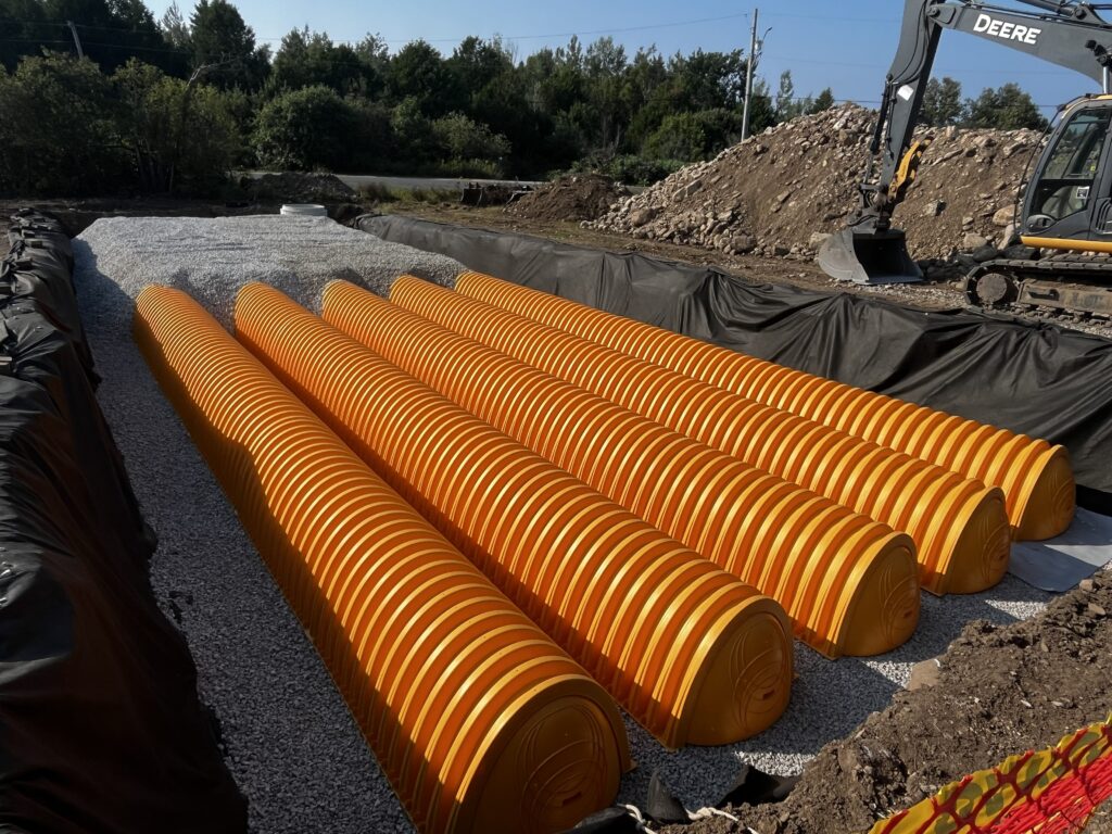
Stuart Crisp, UK manager of Advanced Drainage Systems (ADS), considers the case for open or closed bottom below ground attenuation structures and how high groundwater can influence design.
The starting point for designing a below ground attenuation structure should be whether the system can have an open bottom to facilitate infiltration of runoff or needs to be lined where all the collected rainwater is passed downstream to a water body or storm sewer via an outlet. The second, closely related question is what happens if groundwater rises around the installation.
Open-bottom systems are generally the preferred configuration where site conditions and regulations allow infiltration. They allow stored stormwater to discharge through the underlying soil, providing treatment through the subsoil and potentially adding a volume safety factor based on the soil’s infiltration capacity.
Arch-shaped chambers are particularly suited to this approach, with the majority of installations and designs using an open-bottom arrangement. Where significant infiltration is undesirable or cannot be permitted, however, a suitable liner can convert the same infiltration system into a sealed attenuation facility.
That distinction is important because a closed-bottom, sealed system introduces a different set of hydraulic and geotechnical considerations. Once the storage volume is sealed, the designer must manage both the water retained within the system and the groundwater acting outside it. High groundwater can generate hydrostatic uplift beneath a lined structure and, unless the installation has sufficient resistance, the result can be flotation, displacement or instability.
Open bottom or lined?
Open-bottom attenuation makes use of the natural permeability of the site and works with the underlying soil. This can assist stormwater management by allowing infiltration beneath the tank. If the tank uses a combination of infiltration and an outlet connection, it can also reduce the volume that ultimately has to be discharged through the controlled outlet.
A lined system is appropriate where site conditions preclude significant infiltration or where containment is required to protect groundwater or surrounding infrastructure. Lined attenuation systems are also required if to be adopted by a water company in England as a defined flow path is required in order to meet the legal definition of a sewer. ADS’s Technical Note 6.50 (TN 6.50) identifies viable means of creating watertight attenuation for the StormTech arch-shaped system.
The choice of liner is only part of the design. TN 6.50 recommends, for example, that a sealed system must also include adequate high-flow protection. The high-flow control should pass the peak flow without overtopping the liner, with the weir and associated freeboard established so that the maximum water level remains below the liner crest. Depending on the design, this can be achieved through an upstream bypass or a downstream overflow arrangement.
The groundwater question
For closed-bottom systems, groundwater should be treated as a primary design input rather than an afterthought. Groundwater levels are often highest in winter, but seasonal behaviour varies, and groundwater rebound can cause levels to rise after abstraction ceases. A design based only on normal or currently observed groundwater conditions may therefore underestimate the maximum uplift condition.
Where groundwater rises above the base of a sealed tank, the pressure acting upwards is effectively hydrostatic buoyancy. The critical issue is not simply the nominal weight of the tank itself. TN 6.50 notes that an arch-shaped system may be heavier than the buoyant force overall while still experiencing a limiting stability condition in which buoyant pressure exceeds the resistance pressure directly beneath the chambers. This can cause heave of the bedding and lead to instability.
The preferred approach is therefore to avoid installing lined attenuation systems below groundwater where possible. Where gravity discharge permits groundwater control, an underdrain beneath the liner can be used. Where buoyant forces remain possible, the installation must be designed so that its weight provides sufficient resistance to uplift and avoids the risk of heave in localised areas.
Using mass to resist uplift
The principle is straightforward: the installed system needs sufficient mass to counteract the maximum hydrostatic uplift force. The way that mass is provided depends on the type of attenuation structure.
Traditional concrete tanks and pipes may derive substantial resistance from their own weight, but resistance to flotation due to self-weight should still be verified by calculation rather than assumed. Lightweight geocellular systems generally require additional resistance, commonly in the form of a reinforced concrete slab above the tank.
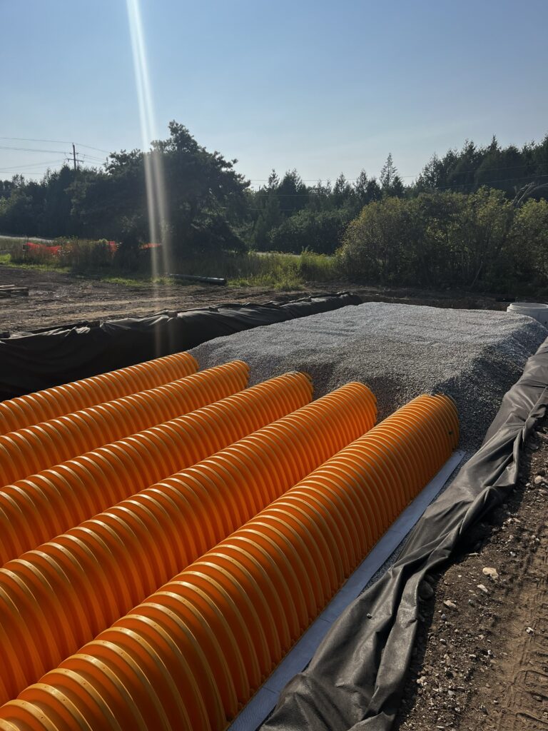
Arch-shaped chambers have a different advantage. They are installed within a substantial volume of embedment stone, which contributes significantly to the overall mass of the installation. That embedment can provide the resistance required to counteract uplift without adding a separate concrete slab.
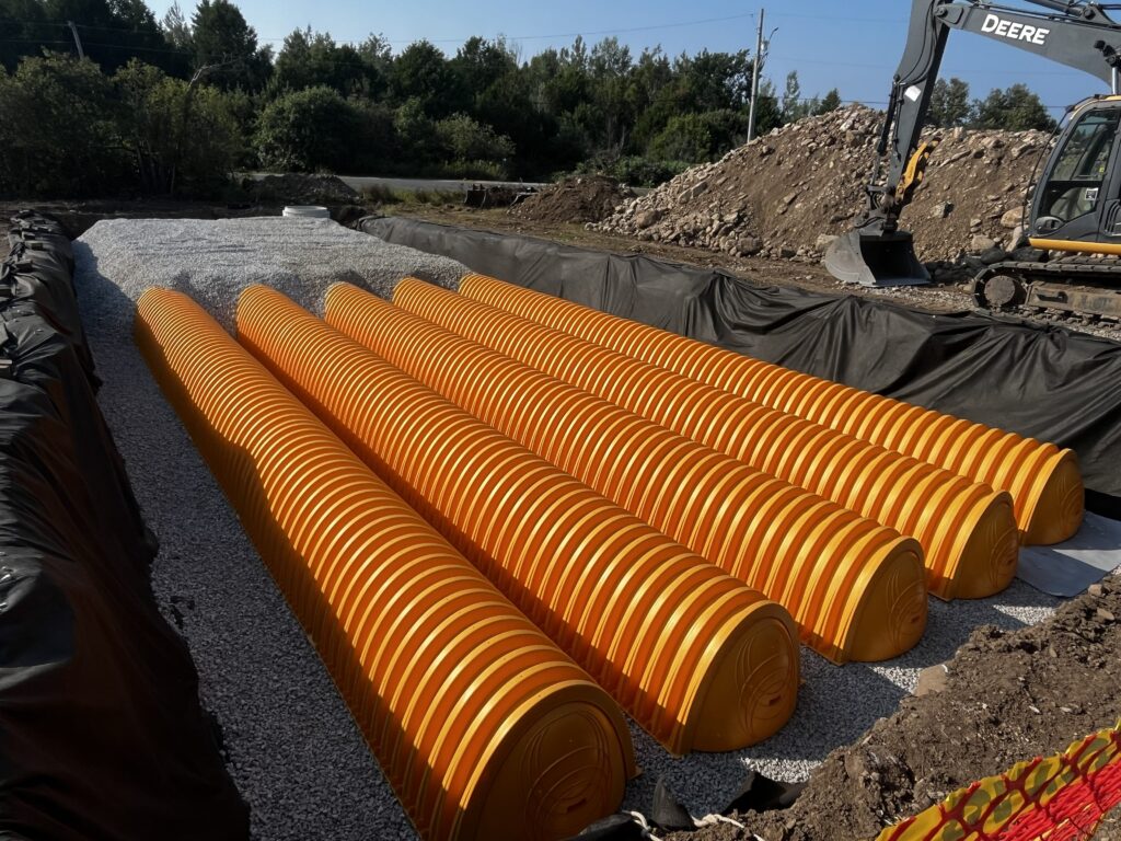
Importantly, the liner itself should not be relied upon as the principal means of resisting flotation. TN 6.50 deliberately excludes any structural contribution from the liner and reinforcement when calculating uplift resistance, instead relying on the weight of the foundation stone, or of stone and select fill, beneath the StormTech chambers.
TN 6.50 provides a design method for determining the required bedding thickness from the maximum groundwater elevation, the bulk density of the bedding material and a safety factor. The calculation deliberately ignores any structural contribution from the liner or reinforcement and relies on the weight of stone or stone and select fill beneath the chambers.
ADS recommends using a conservative stone bulk density where the actual material density is not known, and gives a typical minimum safety factor of 1.25, subject to the consulting engineer’s judgement.
An alternative is a reinforced concrete slab designed specifically to resist uplift while transferring imposed loads into the underlying ground.
Structural design remains soil-structure design
The flotation question sits alongside the more familiar structural loading requirements. These include short-term live loads such as traffic, intermediate-duration loads such as parked vehicles, and long-term earth loads. Performance of flexible thermoplastic systems depends heavily on interaction with the surrounding aggregate, backfill and soil. Effective embedment design allows loads to be transferred through the soil structure, while poor installation or inadequate backfill can result in excessive loads leading to deformation or failure.
Long-term behaviour is also significant. Polypropylene and polyethylene are durable in stormwater environments, but their mechanical properties can reduce under sustained loading, making creep and long-term strain important considerations.
Assessment of arch-shaped StormTech chambers using Eurocode load cases, including minimum and maximum cover, fatigue and braking forces, with long-term material derating incorporated into the analysis reveals all scenarios remain below 100% structural capacity utilisation, with installations up to maximum cover depths producing an average structural capacity factor of 77%.
For UK projects, the implication is clear: attenuation structures can be designed for Eurocode load models, but successful performance depends on treating the installation as a complete soil-structure system. Open-bottom systems can exploit the infiltration capacity of the site; closed-bottom systems can provide controlled storage where infiltration is unsuitable. In either case, groundwater levels, uplift, embedment, loading, creep and installation quality need to be considered together.
The most robust below ground attenuation design is therefore not simply a choice of material or product. It is a decision about how storm water is intended to move through the system, where the groundwater can rise to, and how the completed installation will resist both downward, upward and transverse forces throughout its service life. ADS offers comprehensive technical support for design, installation and maintenance; as well as training and a CPD on below ground SuDS attenuation and treatment covering legislation, best practice and comparable systems. For more information, visit www.adspipe.co.uk.
Flood Industry September 2026
© Copyright 2026. All rights reserved | Privacy Policy