Author Archives: admin
Why ‘install as per manufacturer’s instructions’ is not enough
A competent design for a buried drainage structure must encompass the performance of the product itself, the materials around it and all the interactions in that system, says Stuart Crisp, UK manager of Advanced Drainage Systems (ADS).
It is common to receive drawings for buried drainage structures which simply say ‘install as per manufacturer’s instructions.’ That’s a risky strategy which does not ensure that a SuDS or other drainage system will perform as the designer intended.
When considering the structural integrity of a buried drainage product, such as below-ground SuDS attenuation assets, the designer must consider the whole system: the performance of the product itself; the embedment material and how the product interacts with it; the subgrade material surrounding the excavation and its performance; and the loadings which will be applied.
Failure to appreciate all these elements can lead, in a worst-case scenario, to failure of that structure. For instance, CIRIA C737 structural and geo-technical design of modular geo-cellular drainage systems, provides a list of the main contributing factors to most failures of such structures. The first two are: insufficient appreciation of the importance of an appropriate structural and geo-technical design; and failure to consider particular ground conditions on the site or not allowing for deformation of theunits.
CIRIA C737 underlines the fact that a competent engineer should oversee the design and installation of geo-cellular tanks or crates. And it points out that the responsible engineer should be experienced in ground engineering.
For below-ground SuDS attenuation products, the design approach will be fundamentally different, depending on the type of product deployed, whether crate large-diameter pipe or arch-shaped structure. It is also important to note that systems based around pipes behave very differently,depending on what material the pipe is made of.BS 9295:2020 Guide to the structural design of buried pipes explains that the stiffness of the native soil surrounding a pipe can be particularly important for a flexible pipe, such as a plastic one. Flexible pipes deflect on loading into an oval shape and can develop significant lateral earth pressure around them. On the other hand, pipes made from rigid materials, such as concrete or clay, do not deflect and therefore take most of the loading themselves.
Below-ground attenuation crates are subject to lateral loading, as well as to loading from above. So, the designer must factor in the type of material around the product, as well as any loading due to the presence of groundwater.
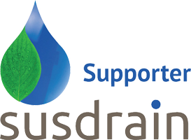
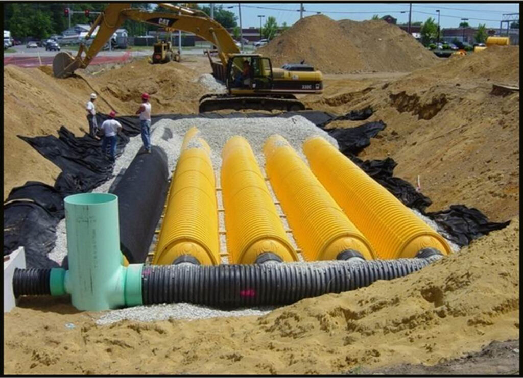
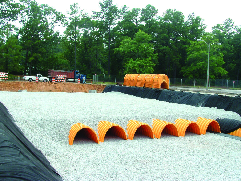
For buried arch-shaped structures, the distribution of loading is different again. The arch shape concentrates the overburden loads through the embedment stone to the spaces between the feet of the arches. The loads are then transferred through a layer of foundation stone to the native subgrade beneath.
Manufacturers should provide technical guidance related to the loading and interactions of their products with the native soil. For instance, ADS’s technical note TN6.22 StormTech Subgrade Performance Considerations does this for arch-shaped chambers.
One of the risks with buried drainage structures is that design responsibilities between the client, designer and manufacturer are often unclear which can mean that the contractor is left to select a product without sufficient information. This risk can be mitigated by a more rigorous approach in the early stages of design.
Recycled aggregate and below-ground SuDS
Recycled aggregate could be used more frequently for installation of below-ground attenuation assets, says Stuart Crisp, UK manager of Advanced Drainage Systems(ADS).
Substituting recycled aggregate for virgin aggregate helps retain natural resources for future generations and can come with cost benefits. Although there is an opportunity to do this with below-ground attenuation assets in sustainable drainage systems (SuDS), contractors often choose to go with what they know–which is the ‘safe’ route of virgin aggregates.
In specifying recycled aggregates, designers and contractors should be aware of the relevant standards, together with any technical guidance from the manufacturer of the attenuation product. BS EN 13242 (+A1:2013) sets out the properties required for aggregates produced from natural, manufactured or recycled materials for hydraulically bound and unbound materials for civil engineering works. Reputable suppliers will provide recycled aggregate with a CE mark to demonstrate conformity to the standard.
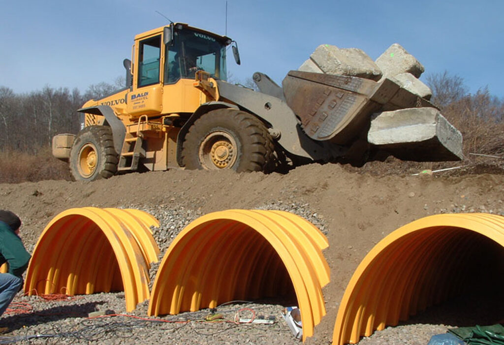
Different product manufacturers may have additional requirements for recycled aggregate which is to be used in below-ground SuDS attenuation systems to ensure that it performs its intended functions. For instance, ADS Pipe’s technical guidance for recycled aggregate for its StormTech system calls for a 20/40mm aggregate which is clean, crushed and angular, with less than 5% fines. The reason for limiting fines is that the void space between the aggregate needs to be preserved to allow for the storage and movement of the water through the matrix of aggregate.
Specifications should set out an average porosity for the aggregate. Porosity is the volume of voids over the total volume; this is sometimes confused with void ratio which is the volume of voids over the volume of solids which can lead to installed systems not meeting design requirements.
Other factors to consider when selecting recycled aggregate include the nature of the ground and the ground water and whether there are any potentially aggressive substances present. Sulphites carried in ground water, for example, could react with recycled concrete aggregate and degrade it over time.
Different types of below-ground attenuation systems require different proportions of aggregate to manufactured product. Crates deploy small amounts of aggregate around their perimeter, large-diameter pipes and arch-shaped attenuation products use a greater proportion of aggregate.
With arch-shaped attenuation products, the aggregate around the arches has a dual purpose. It provides structural support, with the elliptical shape of the arches forming the aggregate around them into stone arches and structural columns, transferring the loads away from the chambers into the stiffer material surrounding them. The aggregate also provides additional storage volume which contributes to the efficiency of the attenuation system in terms of its water storage capability.
Recycled aggregate will not necessarily have lower embodied carbon than virgin aggregate, which tends to be supplied from quarries close to the point of installation.
Recycled aggregate can come at a lower cost than its virgin counterpart, again depending largely on transportation distances.
Generally speaking, attenuation products requiring a higher aggregate-to-product ratio tend to have a lower overall carbon footprint per cubic metre of storage than those requiring less aggregate-to-product.