
Contact ADS UK on 0203 442 0607 or click here
Contact ADS UK on 0203 442 0607 or click here
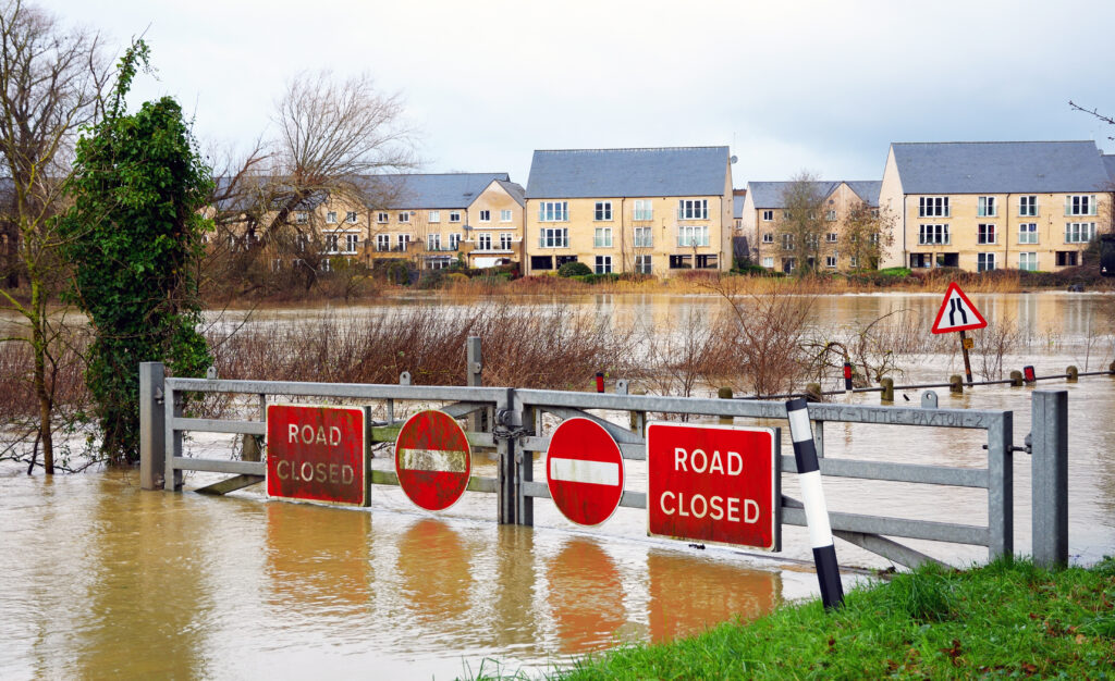
In the second part of a two-part series, Stuart Crisp, UK manager of Advanced Drainage Systems (ADS) – having considered the case for open or closed bottom below ground attenuation structures – looks at designing against possible uplift and flotation.
The preferred approach is to avoid installing lined attenuation systems within or in close proximity to high groundwater where possible. Where gravity discharge permits groundwater control, an underdrain beneath the liner can be used. Where buoyant forces remain possible, the installation must be designed so it provides sufficient resistance to uplift and avoids localised heave.
This is normally achieved by providing the attenuation tank with sufficient weight.
How that weight is provided depends on the attenuation structure.
Traditional concrete tanks and pipes may derive substantial resistance from their own weight, but resistance to flotation through self-weight should still be verified by calculation rather than assumed. Lightweight geocellular systems generally require additional resistance, commonly using a reinforced concrete slab above the tank, which can add significantly to the installed cost.
Arch-shaped chambers have a different advantage. The embedment stone surrounding the chambers can provide the resistance required to counteract uplift without additional measures.
Importantly, the liner itself should not be relied on as the principal means of resisting flotation. ADS Technical Note 6.50 (TN 6.50) deliberately excludes structural contribution from the liner and reinforcement when calculating uplift resistance, instead relying on the weight of foundation stone, or stone and select fill, beneath the StormTech chambers.
TN 6.50 provides a method for determining required bedding thickness from maximum groundwater elevation, bedding-material bulk density and a safety factor. The calculation ignores structural contribution from the liner or reinforcement. ADS recommends a conservative stone bulk density where actual material density is unknown, and gives a typical minimum safety factor of 1.25, subject to the engineer’s judgement. An alternative is a reinforced concrete slab designed specifically to resist uplift while transferring imposed loads into the surroundings.
Flotation sits alongside the structural loading requirements. These include short-term live loads such as traffic, temporary loads such as parked cars and long-term earth loads. Flexible thermoplastic systems depend heavily on interaction with surrounding aggregate, backfill and soil. Long-term creep and strain must also be considered because mechanical properties can reduce under sustained loading.
For UK projects, StormTech arch-shaped chambers have been assessed using Eurocode load cases, including minimum and maximum cover, fatigue and braking forces, with long-term material derating incorporated into the analysis. The assessment reports that in all load cases, structural capacity utilisation is below 100%, with installations up to maximum cover depths producing the most onerous conditions, with an average structural capacity factor of 77%.
The design principle is therefore to treat attenuation as a complete soil-structure system: product/system selection, water conveyance and storage, groundwater interaction, loading, creep, embedment detail and installation quality must be considered together.
New Civil Engineer November 2026
© Copyright 2026. All rights reserved | Privacy Policy